Method and System For Localizing Parts of an Object in an Image For Computer Vision Applications

a computer vision and image technology, applied in the field of computer-aided analysis of images, can solve the problems of false detection, large image support, and difficulty in face detection from a single image,

Active Publication Date: 2012-12-06
KRIEGMAN BELHUMEUR VISION TECH
View PDF13 Cites 82 Cited by
  • Summary
  • Abstract
  • Description
  • Claims
  • Application Information

AI Technical Summary

Benefits of technology

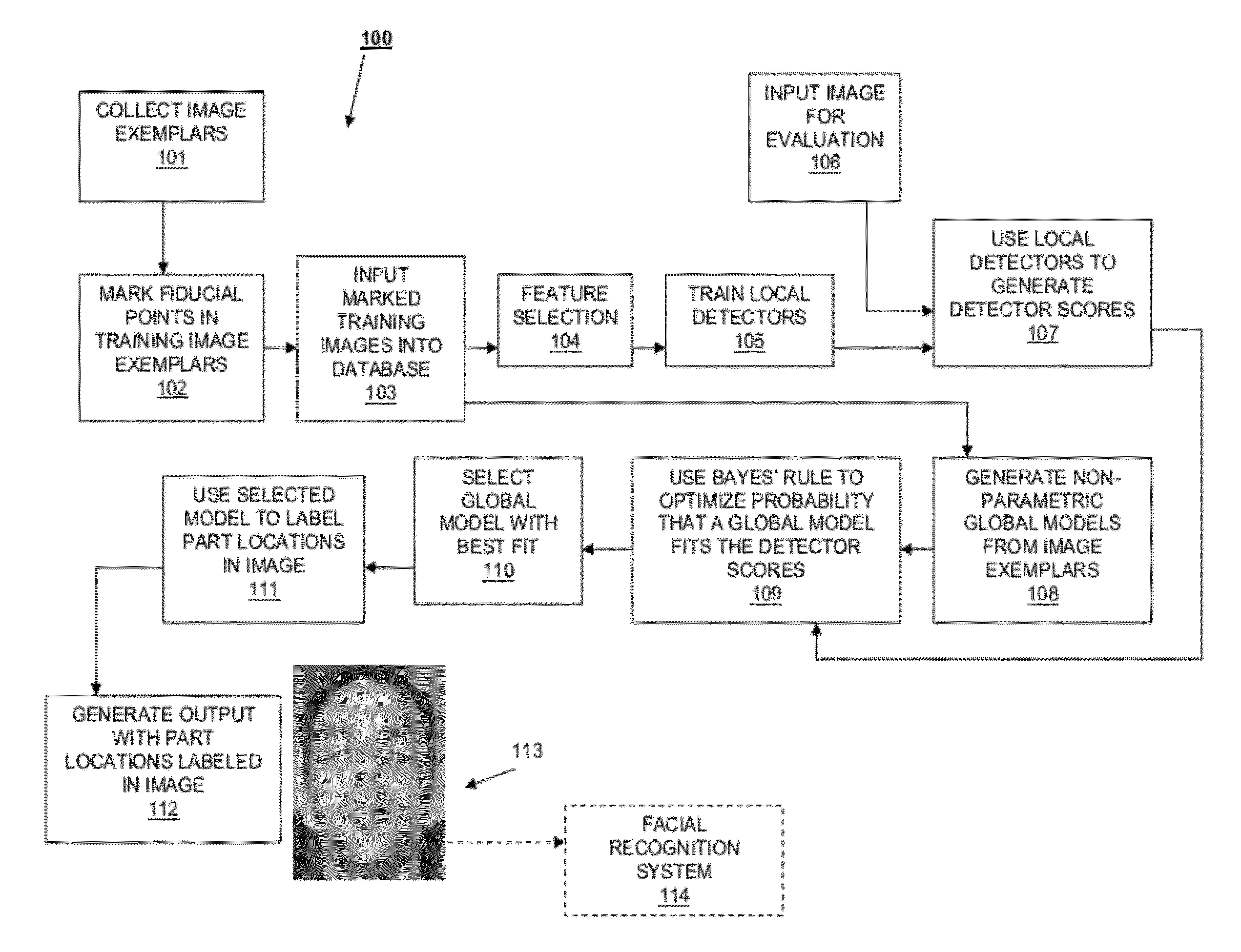
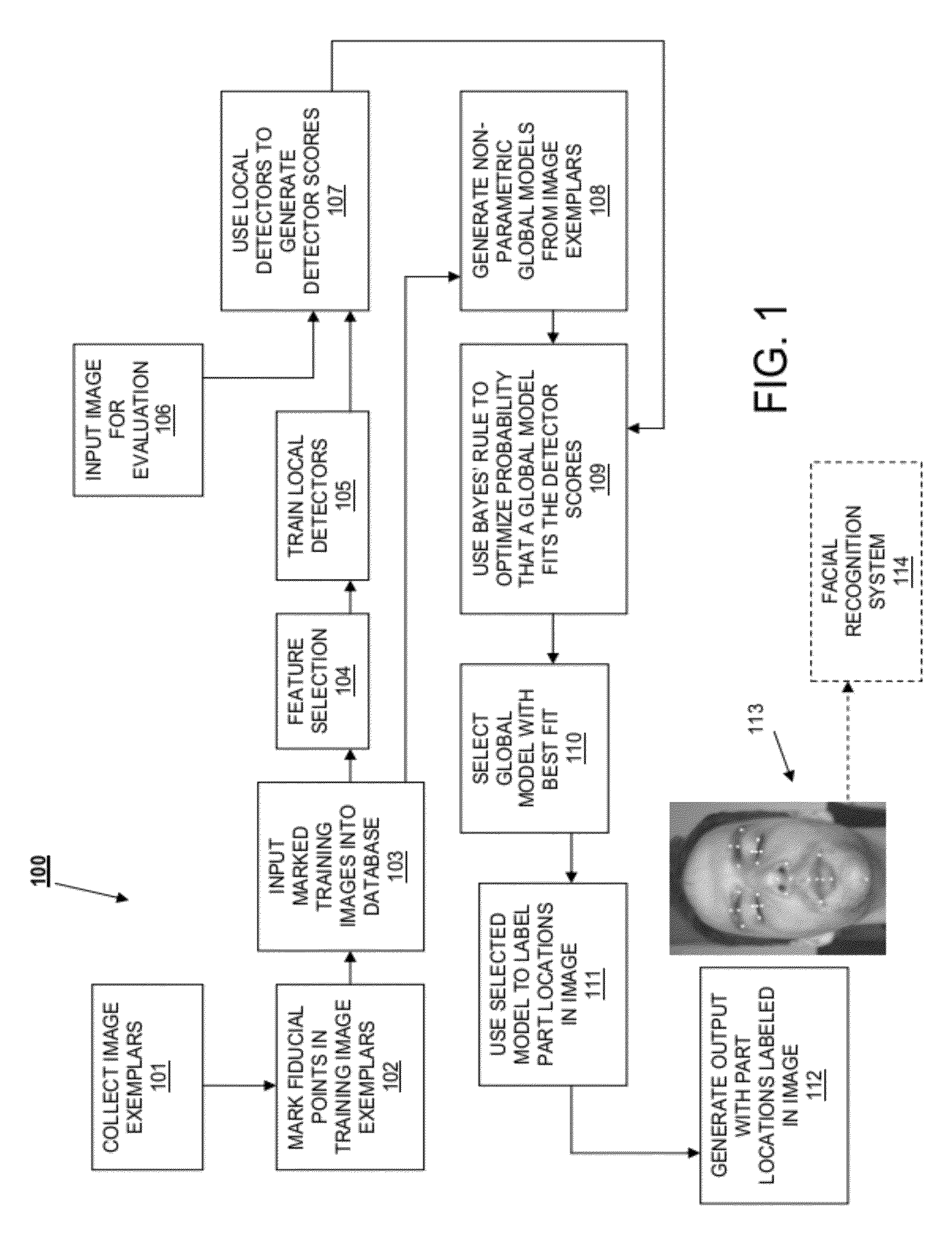
[0025]In one aspect of the invention, the facial feature localization method is formulated as a Bayesian inference that combines the output of local detectors with a prior model of face shape. The prior on the configuration of face parts is non-parametric, making use of a large collection of diverse, labeled exemplars. Hidden (latent) variables are introduced for the identity and parts locations within the exemplar to generate fiducial locations in a new image. The hidden variables are marginalized out, but they nonetheless provide valuable conditional independencies between different parts. To marginalize efficiently, a RANdom SAmple Consensus (RANSAC)-like process to sample likely values of the hidden variables. This ultimately leads to part localization as a combination of local detector output and the consensus of a variety of exemplars and poses that fit t

Problems solved by technology

However, face detection from a single image is challenging because of variability in scale, location, orientation, and pose.
As a result, their detection may require larger image support.
False detections occur often, even for well-trained classifiers, because portions of the image have the appearance of a fiducial under some imaging condition.
For example, a common error is for a “left corner of left eye” detector to respond to the left corner of the right eye.
As pointed out

Method used


Image

  • Method and System For Localizing Parts of an Object in an Image For Computer Vision Applications
  • Method and System For Localizing Parts of an Object in an Image For Computer Vision Applications
  • Method and System For Localizing Parts of an Object in an Image For Computer Vision Applications

Examples


examples

[0080]The present invention focuses on localizing parts in natural face images, taken under a wide range of poses, lighting conditions, and facial expressions, in the presence of occluding objects such as sunglasses or microphones. Existing datasets for evaluating part localization do not contain the range of conditions.

[0081]Since researchers have recently reported results on BioID, the results produced by the present invention are compared to prior results on BioID. Like most datasets used to evaluate part localization on face images, BioID contains near-frontal views and less variation in viewing conditions than LFPW.

[0082]LFPW consists of 3,000 faces from images downloaded from the web using simple text queries on sites such as google.com, flickr.com, and yahoo.com. The 3,000 faces were detected using a commercial, off-the-shelf (COTS) face detection system. Faces were excluded only if they were incorrectly detected by the COTS detector or if they contained text on the face. Not...


PUM


Abstract

A method is provided for localizing parts of an object in an image by training local detectors using labeled image exemplars with fiducial points corresponding to parts within the image. Each local detector generates a detector score corresponding to the likelihood that a desired part is located at a given location within the image exemplar. A non-parametric global model of the locations of the fiducial points is generated for each of at least a portion of the image exemplars. An input image is analyzed using the trained local detectors, and a Bayesian objective function is derived for the input image from the non-parametric model and detector scores. The Bayesian objective function is optimized using a consensus of global models, and an output is generated with locations of the fiducial points labeled within the object in the image.

Description

RELATED APPLICATIONS[0001]This application claims the benefit of the priority of U.S. provisional application No. 61 / 492,774, filed Jun. 2, 2011, which is incorporated herein by reference in its entirety.GOVERNMENT RIGHTS[0002]This invention was made with government funding from the Offie of the Chief Scientist of the Central Intelligence Agency. The government has certain rights in the invention.FIELD OF THE INVENTION[0003]The present invention relates to a method for computer-aided analysis of images, and more specifically to a method for localizing features within an image.BACKGROUND OF THE INVENTION[0004]Over the last decade, new applications in computer vision and computational photography have arisen due to earlier advances in methods for detecting human faces in images. These applications include face detection-based autofocus and white balancing in cameras, smile and blink detection, new methods for sorting and retrieving images in digital photo management software, obscurat...

Claims


Application Information

Patent Timeline
IPC IPC(8): G06K9/62G06V10/764
CPCG06K9/00281G06K9/00248G06K9/62G06K9/6278G06V40/171G06V10/764G06F18/24155G06V40/165G06F18/00
Inventor BELHUMEUR, PETER N.JACOBS, DAVID W.KRIEGMAN, DAVID J.KUMAR, NEERAJ
Owner KRIEGMAN BELHUMEUR VISION TECH
Why Eureka
Try Eureka