Ultraviolet Discharge Lamp Apparatuses with One or More Reflectors

a technology of ultraviolet light and reflector, which is applied in the direction of gas discharge lamps, speed/acceleration control, lighting support devices, etc., can solve the problems of affecting the effect of ultraviolet light generation, little or no improvement in the efficiency of ultraviolet light, and affecting the achievement of the goal of uv propagation from a system

Active Publication Date: 2012-12-13
XENEX DISINFECTION SERVICES
View PDF33 Cites 57 Cited by
  • Summary
  • Abstract
  • Description
  • Claims
  • Application Information

AI Technical Summary

Problems solved by technology

Although different types of discharge lamps have been investigated to provide UV light for different applications, little has been done to improve the efficiency of the ultraviolet light generated in apparatuses, particularly with respect to the propagation of the ultraviolet light (i.e., distance and angle of incidence on a target object).
A reason for such a lack of advancement is that many apparatuses having discharge lamps, such as food sterilization and single object disinfection devices, are configured to treat items placed in close proximity and in direct alignment with the lamp and, thus, little or no improvement in efficiency of the UV light may be realized by altering its propagation.
Furthermore, room/area decontamination systems are specifically designed to disperse light over a vast area and, thus, altering UV

Method used


Image

  • Ultraviolet Discharge Lamp Apparatuses with One or More Reflectors
  • Ultraviolet Discharge Lamp Apparatuses with One or More Reflectors
  • Ultraviolet Discharge Lamp Apparatuses with One or More Reflectors

Examples


Embodiment Construction

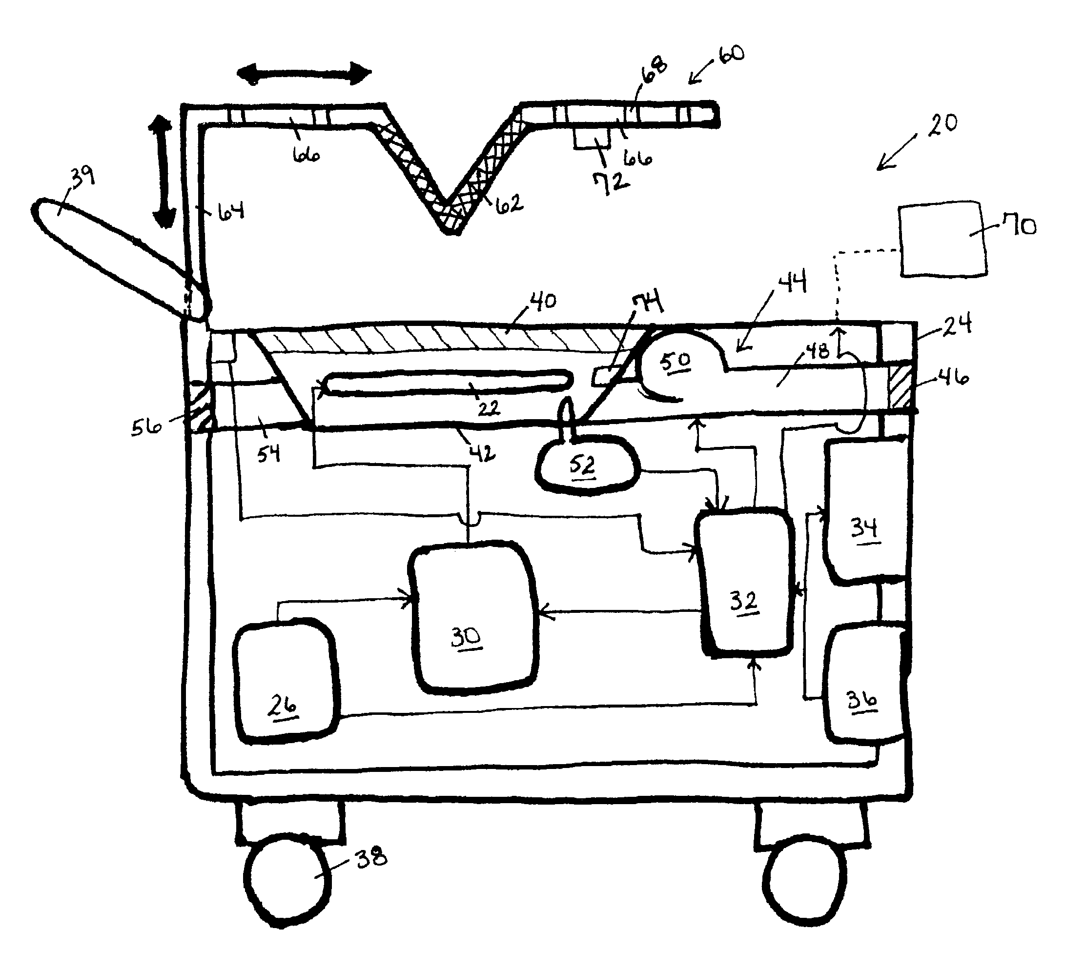
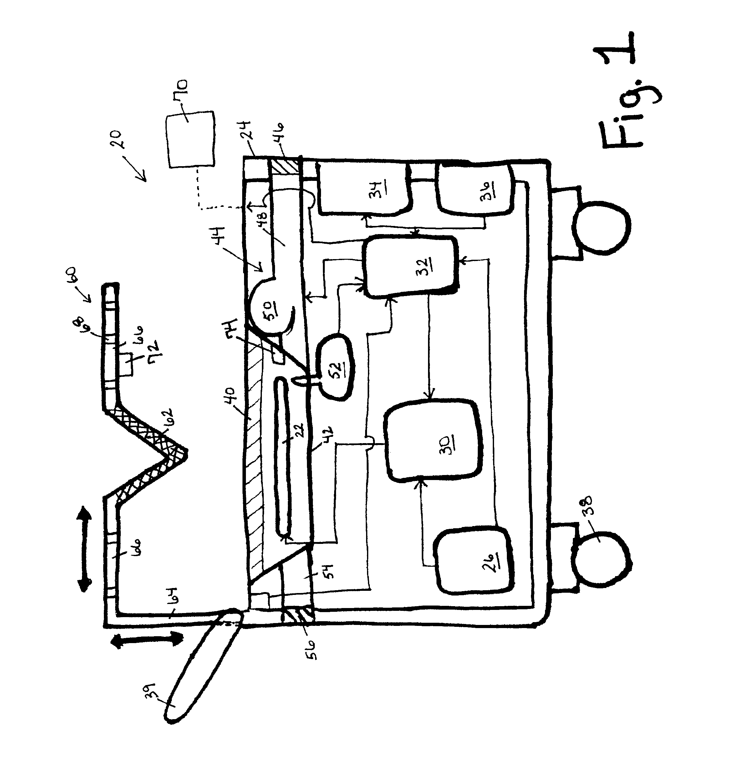
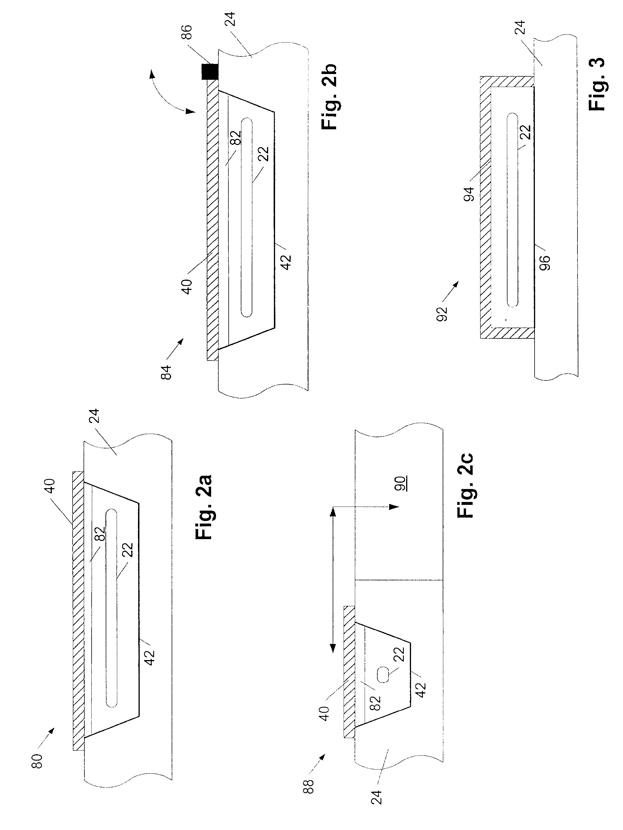
[0022]Turning to the drawings, exemplary embodiments of discharge lamp apparatuses are provided. More specifically, exemplary configurations of apparatuses are shown in FIGS. 1-3 having a discharge lamp arranged lengthwise parallel to a plane of the apparatus at which the lamp is supported (hereinafter referred to as a “horizontally positioned lamp”). In addition, exemplary configurations of apparatuses are shown in FIGS. 4-7 having a discharge lamp arranged lengthwise perpendicular to a plane of the apparatus at which the lamp is supported (hereinafter referred to as a “vertically positioned lamp”). In addition, a system having two discharge lamp apparatuses is shown in FIG. 8. As will be set forth in more detail below, the apparatuses and features described herein are not limited to the depictions in the drawings, including that the discharge lamps are not restricted to “horizontal” and “vertical” positions. Furthermore, it is noted that the drawings are not necessarily drawn to s...


PUM


Abstract

Apparatuses are disclosed which include a discharge lamp configured to emit ultraviolet light, a power circuit configured to operate the discharge lamp, and a reflector system configured to redirect ultraviolet light emitted from the discharge lamp. In some embodiments, the apparatuses include a support structure containing the power circuit and supporting the discharge lamp. In some of such embodiments, the reflector system is configured to redirect ultraviolet light propagating away from the support structure to a region exterior to the apparatus and which is between approximately 2 feet and approximately 4 feet from a floor of a room in which the apparatus is arranged. In other embodiments, the reflector system may be additionally or alternatively configured to redirect ultraviolet light propagating away from the support structure to encircle an exterior surface of the apparatus. In any case, the reflector system may, in some embodiments, include a repositionable reflector.

Description

BACKGROUND OF THE INVENTION[0001]1. Field of the Invention[0002]This invention generally relates to ultraviolet discharge lamp apparatuses and, more specifically, to ultraviolet discharge lamp apparatuses having one or more reflectors and methods of operating such apparatuses.[0003]2. Description of the Related Art[0004]The following descriptions and examples are not admitted to be prior art by virtue of their inclusion within this section.[0005]Discharge lamps are used in a variety of applications to generate ultraviolet (UV) light, including but not limited to polymer curing, food sterilization, fluid and object disinfection, and room / area decontamination. For example, it is known that UV irradiation in the spectrum between approximately 200 nm and approximately 320 nm is effective in deactivating and, in some cases, killing microorganisms, giving reason to the use of ultraviolet light technology for disinfecting and / or sterilizing items. In general, discharge lamps refer to lamps...

Claims


Application Information

Patent Timeline
IPC IPC(8): A61L2/10G21K5/00
CPCA61L2/10H01J61/025A61L9/20A61L2/24A47L11/405H01J61/00F21V21/22F21V21/15A61L2202/16A61L2202/14A47L2201/00A61L2/084F21V7/00F21V21/00H01J61/02A61L2/14A61L2202/25A61L2/18A61L2/20A61L9/015A61L2209/111G02B5/208H01J61/40B01D53/66G05D1/0088G05D13/00A61L2/28G01J1/429G05D2201/0203B01D2257/106
Inventor STIBICH, MARK ANDREWWOLFORD, JAMES BLAINEGARFIELD, ALEXANDER NATHANRATHGEBER, MARTINFRYDENDALL, ERIC MARTIN
Owner XENEX DISINFECTION SERVICES
Why Eureka
Try Eureka