Eureka AIR delivers breakthrough ideas for toughest innovation challenges, trusted by R&D personnel around the world.

Parallel-Connected Ballast Circuits

Inactive Publication Date: 2012-12-13
METROLIGHT
View PDF4 Cites 2 Cited by
  • Summary
  • Abstract
  • Description
  • Claims
  • Application Information

AI Technical Summary

Benefits of technology

[0008]According to embodiments of the present invention there is provided a ballast circuit adapted for converting an input alternating current (AC) mains power received at input terminals to an output alternating current (AC) to supply a load, e.g. a gas discharge lamp. The output terminals of the ballast connect to the load in parallel with another ballast circuit. The ballast circuit is configured to supply the output AC current to the load in parallel with an AC current output of the other ballast circuit. A synchronization module attached at the output is adapted for synchronizing the output alternating current (AC) of the ballast circuit with the AC current output of the other ballast circuit. The synchronization module is typically configured to synchronize ignition outputs of the ballast circuit and said other ballast circuit. The synchronization module is configured to synchronize phase of the output alternating current with phase of the AC current output of the other ballast circuit. The synchronization module may be configured as either a master synchronization module which provides a synchronization signal to the other ballast circuit or a slave synchronization module which receives a synchronization signal from the other ballast circuit. The ballast may include a microprocessor and a communication interface attached thereto. The microprocessor may be configured to be re-programmed through the communications interface to supply to the load a higher AC current than the output AC current previously programmed.
[0009]According to an embodiment of the present invention there is provided multiple ballast circuits with respective AC outputs configured for interconnection in parallel and for supplying alternating curre

Problems solved by technology

Once the arc is started, the arc heats and evaporates the metal salts forming a plasma, which greatly increases the intensity of light produced by the arc and reduces its power consumption.
If a gas-charge lamp were connected to a constant-voltage power supply, the lamp would draw an increasing amount of current until it is destroyed.

Method used


Image

  • Parallel-Connected Ballast Circuits
  • Parallel-Connected Ballast Circuits
  • Parallel-Connected Ballast Circuits

Examples


Embodiment Construction

[0015]Reference will now be made in detail to embodiments of the present invention, examples of which are illustrated in the accompanying drawings, wherein like reference numerals refer to the like elements throughout. The embodiments are described below to explain the present invention by referring to the figures.

[0016]Before explaining embodiments of the invention in detail, it is to be understood that the invention is not limited in its application to the details of design and the arrangement of the components set forth in the following description or illustrated in the drawings. The invention is capable of other embodiments or of being practiced or carried out in various ways. Also, it is to be understood that the phraseology and terminology employed herein is for the purpose of description and should not be regarded as limiting.

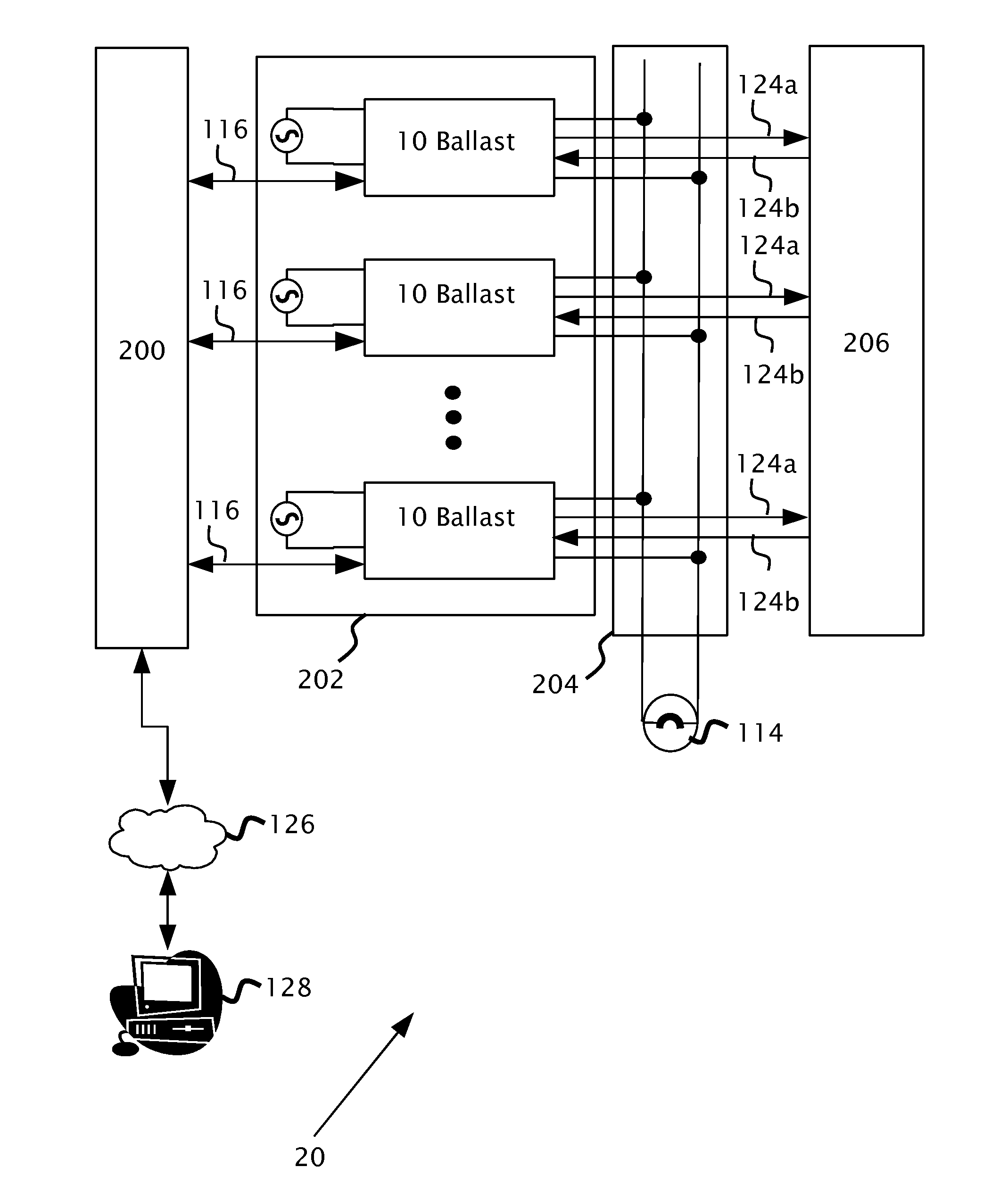
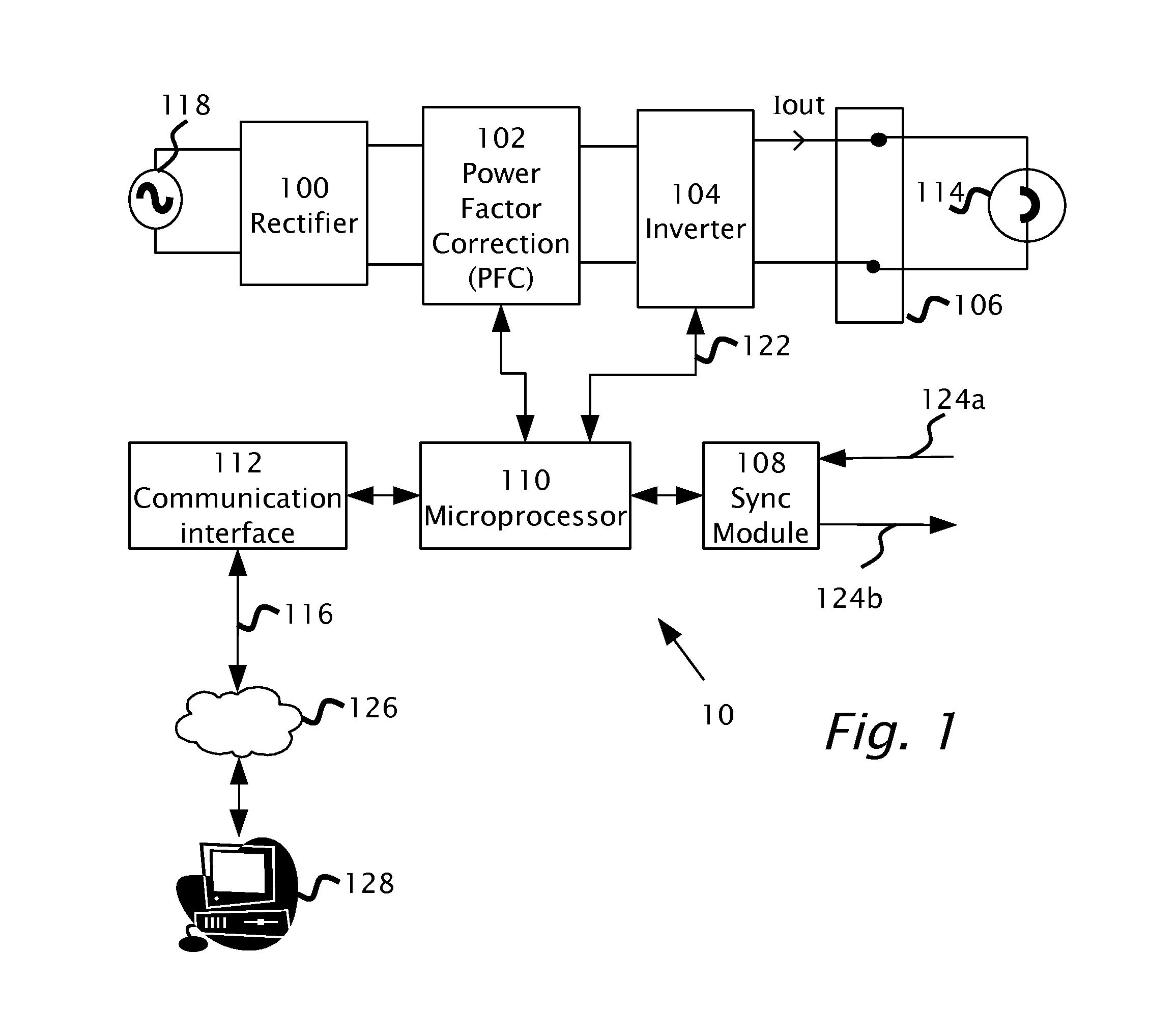
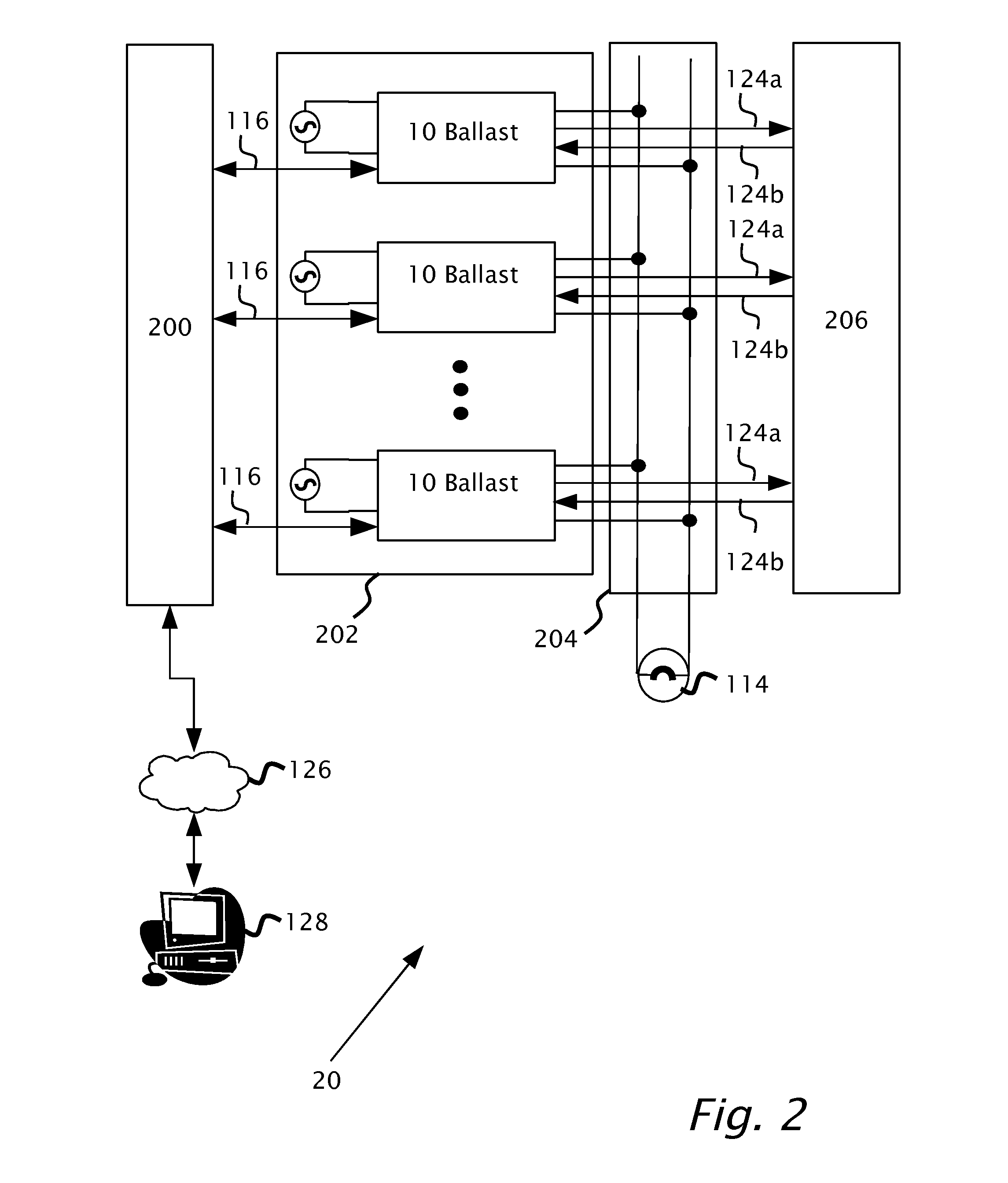
[0017]By way of introduction, embodiments of the present invention are directed to allow for fail-safe operation of gas discharge lamps in a ballast lig...


PUM


Abstract

A ballast circuit adapted for converting an input alternating current (AC) mains power received at input terminals to an output alternating current (AC) to supply a load, e.g. a gas discharge lamp. The output terminals of the ballast connect to the load in parallel with another ballast circuit. The ballast circuit is configured to supply the output AC current to the load in parallel with an AC current output of the other ballast circuit. A synchronization module attached at the output is adapted for synchronizing the output alternating current (AC) of the ballast circuit with the AC current output of the other ballast circuit. The synchronization module is configured to synchronize phase of the output alternating current with phase of the AC current output of the other ballast circuit.

Description

BACKGROUND[0001]1. Technical Field[0002]The present invention relates to ballast circuits for gas-discharge lamps and in particular a system and method for load balancing between ballasts and improving reliability of lighting systems.[0003]2. Description of Related Art[0004]Gas-discharge lamps include fluorescent lamps, low and high pressure sodium lamps, metal halide lamps and high-intensity discharge (HID) lamps. A high-intensity discharge (HID) lamp produces light by means of an electric arc between tungsten electrodes housed inside a translucent or transparent fused quartz or fused alumina arc tube. The tube is filled with both gas and metal salts. The gas facilitates the arc's initial strike. Once the arc is started, the arc heats and evaporates the metal salts forming a plasma, which greatly increases the intensity of light produced by the arc and reduces its power consumption.[0005]Ballasts are used where an electrical load, e.g. gas-discharge lamp cannot effectively regulate...

Claims


Application Information

Patent Timeline
IPC IPC(8): H05B41/16H05B37/03
CPCH05B41/288
Inventor HOLLANDER, JONATHAN
Owner METROLIGHT
Why Eureka
Eureka Blog
Learn More