Telescopic gun sight with magnification-invariant reticle

a reticle, magnification-invariant technology, applied in the field of telescopic gun sights, can solve the problems of excessive reticle enlargement and shrinkage, difficult to see, and obscuring the field of view,

Inactive Publication Date: 2012-12-13
JAHROMI OMID
View PDF5 Cites 18 Cited by
  • Summary
  • Abstract
  • Description
  • Claims
  • Application Information

AI Technical Summary

Problems solved by technology

The only draw back of a rifle scope with FFP reticle is that the reticle could appear too small (therefore difficult to see) at low magnification and too large (therefore obscuring the field of view) at high magnification.
It is clear from this illustration that for FFP rifle scopes with a large zoom range, excessive reticle enlargement and shrinkage becomes a major problem.

Method used


Image

  • Telescopic gun sight with magnification-invariant reticle
  • Telescopic gun sight with magnification-invariant reticle
  • Telescopic gun sight with magnification-invariant reticle

Examples


first embodiment

A. First Embodiment of the Invention

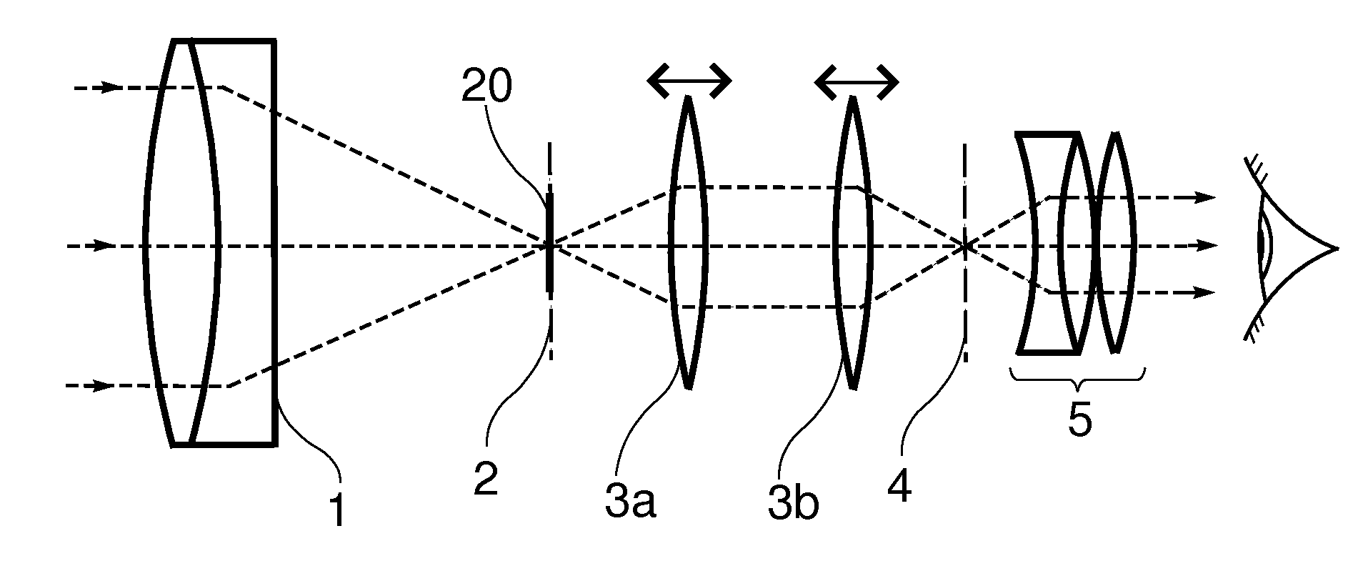
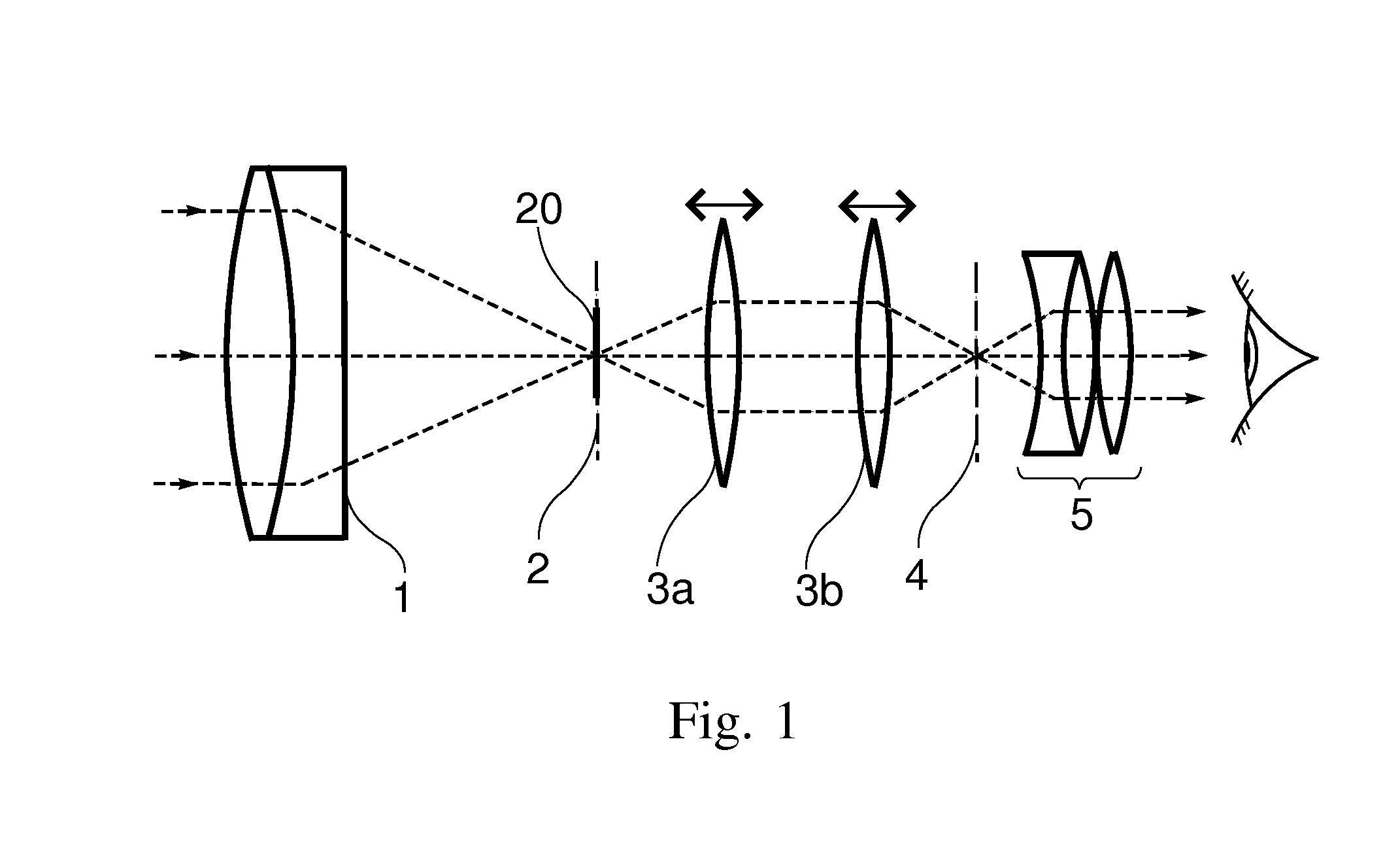
[0029]In accordance with a first embodiment of the invention, a zoom telescopic gun sight comprises an objective lens, a magnification-invariant (MI) reticle, an image relay means with variable magnification, and an eye piece. FIG. 1 shows a side-view schematic illustrating the arrangement of the elements in accordance to the first embodiment of the invention. FIGS. 4a to 4d depict a plurality of MI reticle shapes in accordance to the first embodiment of the invention.

[0030]With reference to FIG. 1, the objective lens 1 forms a first image of a distant target at the objective focal plane 2. This first image is laterally reversed and upside-down. An image relay means, shown symbolically in FIG. 1 comprising of a pair of convex lenses 3a and 3b, takes the first image formed by the objective lens and produces a laterally-correct and up-right second image at the eyepiece focal plane 4. Finally, an eyepiece 5 converts the second image into a virtual im...

second embodiment

B. Second Embodiment of the Invention

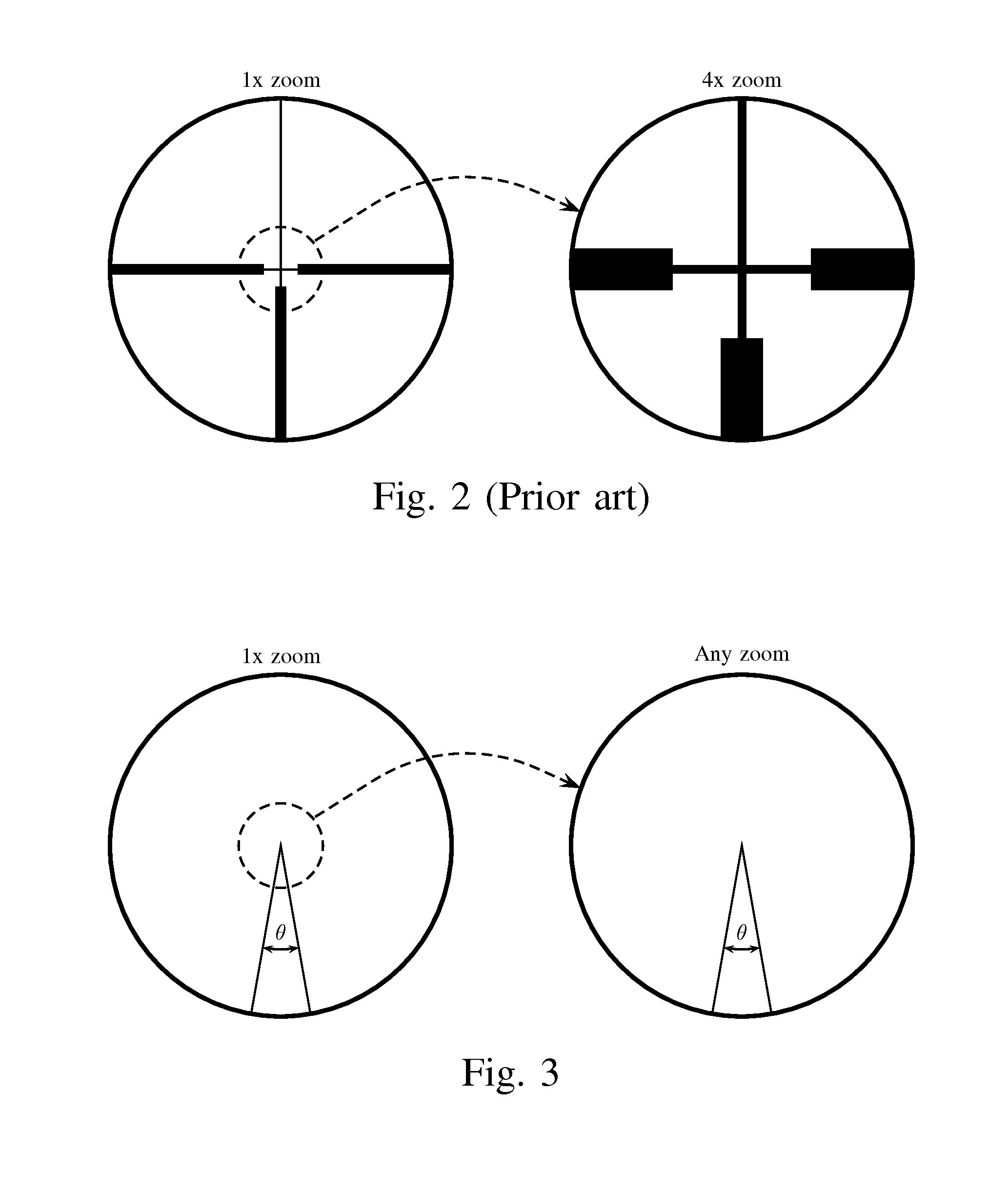
[0037]The telescopic sight described in the first embodiment of the invention has the property that its reticle size appears completely unchanged at any zoom range. While very interesting from an engineering point of view, this level of invariance is not always necessary in practice. In many hunting situations it is sufficient that the reticle remains thin enough at high zoom (not to obstruct the field of view) and thick enough at low zoom (easily visible against the background). In this embodiment we describe a zoom telescopic sight with first focal plane reticle such that the reticle size appears sufficiently unchanged for a finite zoom range.

[0038]In accordance with the second embodiment of the invention, a zoom telescopic gun sight comprises an objective lens, an almost-magnification-invariant (AMI) reticle, an image relay means with variable magnification, and an eye piece. The arrangement of the elements and their function is similar to the...


PUM


Abstract

This invention teaches a telescopic gun sight with a reticle placed at the first focal plane such that the apparent size of the reticle remains substantially invariant when the sight's magnification is changed. According to one embodiment, a telescopic gun sight comprises an objective lens, a magnification-invariant reticle, an image relay means with variable magnification, and an eye piece. The magnification-invariant reticle is designed in accordance to the invention such that its apparent size is not affected by change in the sight's magnification. This invention combines the benefits of telescopic gun sights with first focal plane reticle and second focal plane reticle in a single design.

Description

I. CROSS-REFERENCE TO RELATED APPLICATIONS[0001]Not ApplicableII. FEDERALLY SPONSORED RESEARCH[0002]Not ApplicableIII. SEQUENCE LISTING OR PROGRAM[0003]Not ApplicableIV. FIELD OF THE INVENTION[0004]This application relates to telescopic gun sights. More specifically, this invention relates to telescopic gun sights having variable magnification and a reticle mounted at the objective focal plane.V. BACKGROUND OF THE INVENTION[0005]A telescopic gun sight, commonly called a rifle scope, is a device used to provide an accurate point of aim for firearms such as rifles, handguns and shotguns. A telescopic sight significantly improves the functionality of a firearm by providing the shooter with a simple yet highly accurate means for aiming at distant targets.[0006]A telescopic sight is essentially a Keplerian telescope with an added reticle to designate the point of aim. Reticles are most commonly represented as intersecting lines called “cross hairs” though many variations exist, including...

Claims


Application Information

Patent Timeline
Patent Type & Authority Applications(United States)
IPC IPC(8): G02B23/00
CPCF41G1/38G02B27/32G02B23/145G02B23/10
Inventor JAHROMI, OMID
Owner JAHROMI OMID
Why Eureka
Try Eureka