Optical lens and light-emitting module using the same

a technology of optical lenses and light-emitting modules, applied in the field of optical elements, can solve the problems of reducing the recognition accuracy of the system, limiting the application range, and consuming more power, and achieve the effect of more uniform projection distance and longer projection distan

Inactive Publication Date: 2012-12-13
MILLENNIUM COMM
View PDF9 Cites 6 Cited by
  • Summary
  • Abstract
  • Description
  • Claims
  • Application Information

AI Technical Summary

Benefits of technology

[0007]The present invention proposes an optical lens which has a light-entering curved face and a light-exiting curved face. Preferably, the entering-light curved face can be roughened. Therefore, incident light entering to the proposed optical lens from a light source is first diverged and then converged at a predetermined angle, so as to make the illumination light outputted from the proposed light-emitting module with the optical lens more uniform and have a longer projection distance.

Problems solved by technology

However, LED illumination source consumes more power and it is unable to project illumination light at a far position (such as 200˜300 meters), which therefore limits its range of application.
However, a light pattern of a surface emitting laser is shaped like a donut with a dimmer center area; it easily causes shadow in images so as to decrease recognition accuracy of the system.

Method used


Image

  • Optical lens and light-emitting module using the same
  • Optical lens and light-emitting module using the same
  • Optical lens and light-emitting module using the same

Examples


Embodiment Construction

[0016]The detailed explanation of the present invention is described as follows. The described preferred embodiments are presented for purposes of illustrations and description, and they are not intended to limit the scope of the present invention.

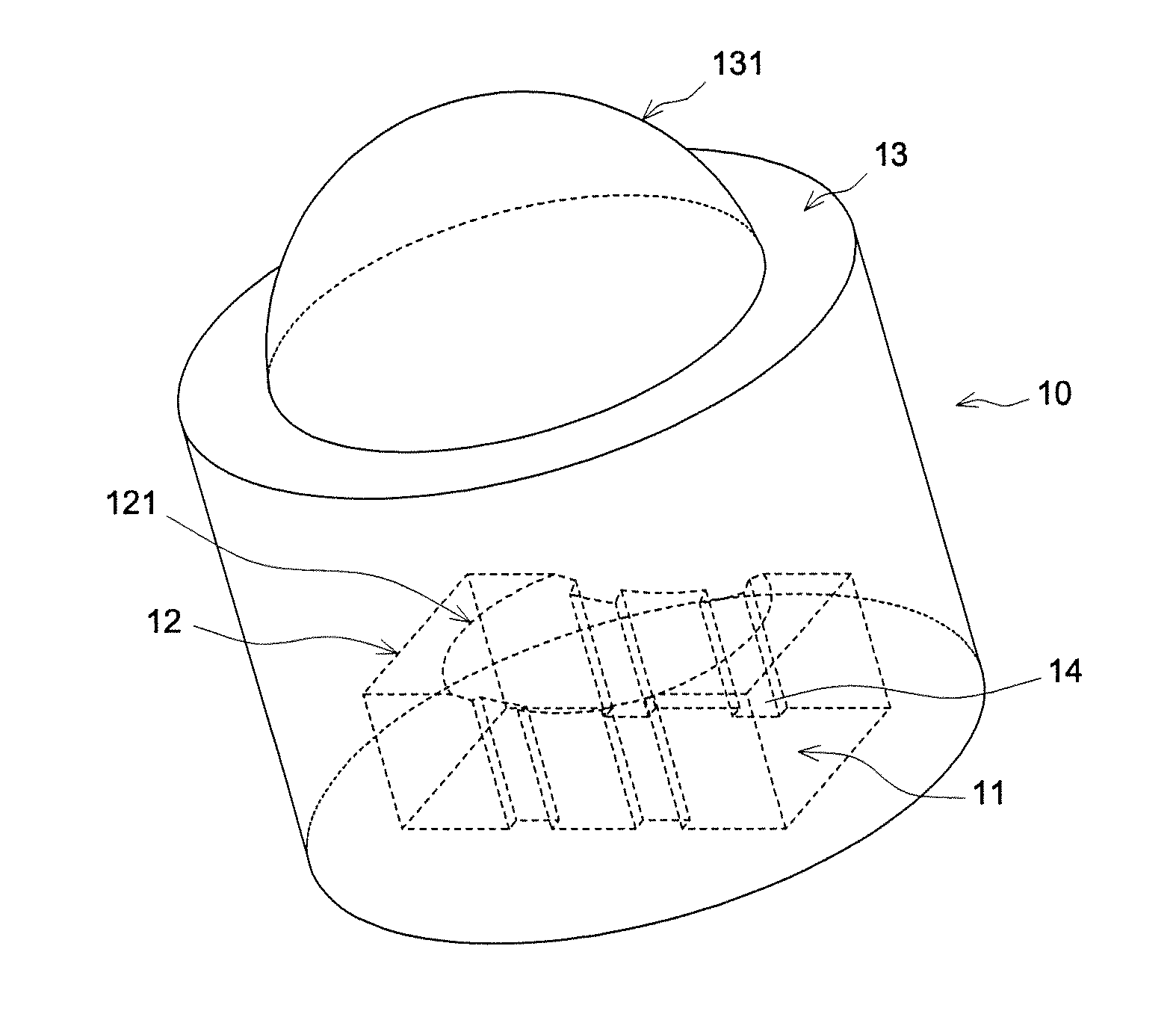
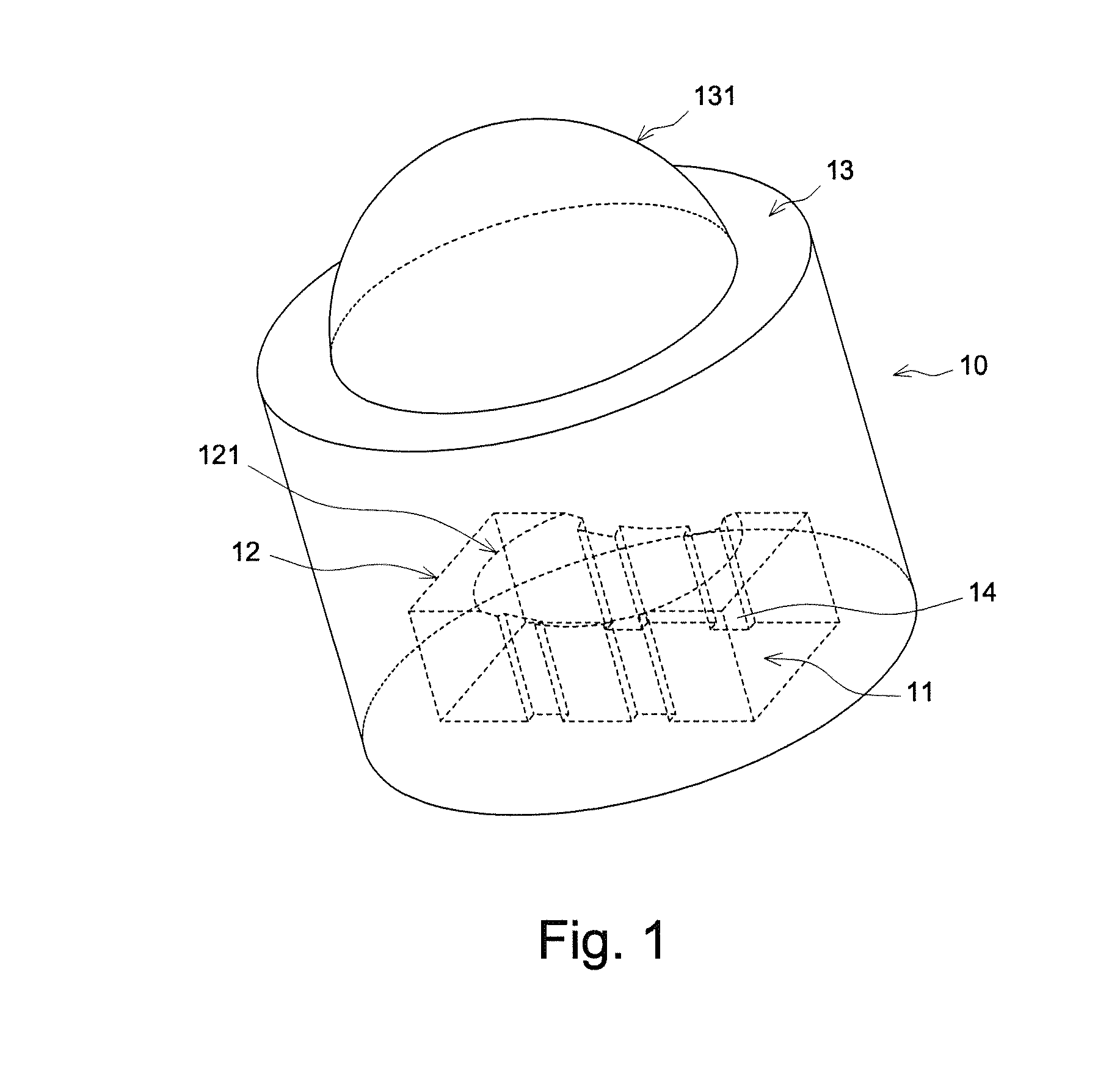
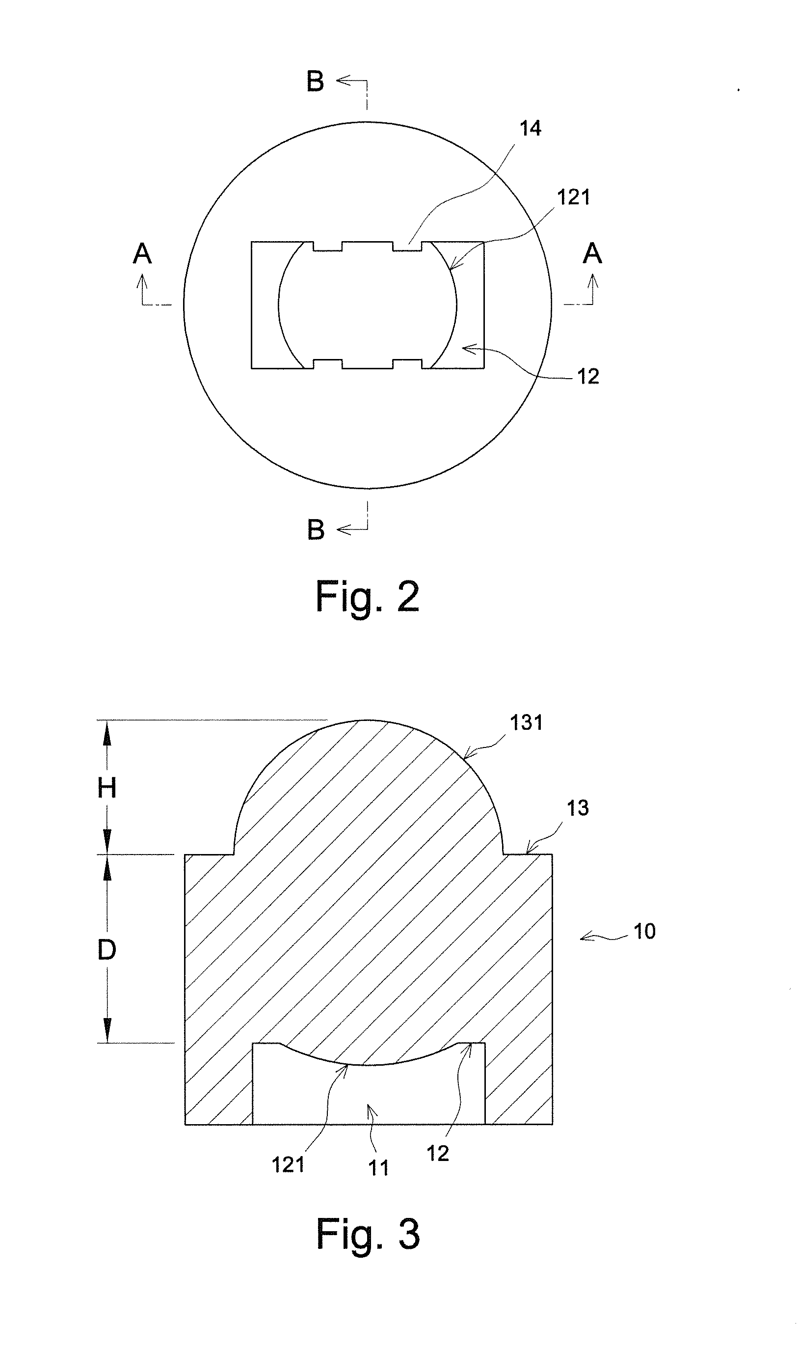
[0017]FIG. 1 shows schematically a stereogram of an optical lens according to an embodiment of the present invention. FIG. 2 shows schematically a bottom-view diagram of the proposed optical lens. FIG. 3 shows schematically a cross-sectional structure of the proposed optical lens along the section line AA in FIG. 2. Referring to FIG. 1, FIG. 2 and FIG. 3, the optical lens according to an embodiment of the present invention comprises a main body 10 including a recess 11. A bottom surface 12 of the recess 11 has a light-entering curved face 121. In one embodiment of the present invention, the light-entering curved face 121 is aspheric. In a preferred embodiment of the present invention, the light-entering curved face 121 is treated to be rou...


PUM


Abstract

An optical lens for modulating light generated by a surface-emitting laser chip is disclosed. The optical lens includes a main body with a recess. A bottom surface of the recess is configured with a light-entering curved face, and an outer surface of the main body opposite to the bottom surface is configured with a light-existing curved face. Here, the recess is for accommodating the surface-emitting laser chip, and the surface-emitting laser chip is arranged a distance from the light-entering curved face. A light-emitting module adopting the aforementioned optical lens is also provided. The aforementioned optical lens would cause the incident light to first diverge and then converge at a predetermined angle, so that the output illuminating light is more uniform and the projecting distance is extended.

Description

BACKGROUND OF THE INVENTION[0001]1. Field of the Invention[0002]The present invention relates to an optical element, and more particularly to an optical lens and a light-emitting module including the same.[0003]2. Description of the Prior Art[0004]Due to security and other commercial needs, infrared surveillance systems or recognition systems have been widely used in the field. These systems of prior art mostly use a plurality of light-emitting diodes (LED) with high efficiency as illumination source. However, LED illumination source consumes more power and it is unable to project illumination light at a far position (such as 200˜300 meters), which therefore limits its range of application.[0005]To overcome the abovementioned shortcomings, laser light source has nowadays been adopted as the illumination source in infrared surveillance systems or recognition systems. However, a light pattern of a surface emitting laser is shaped like a donut with a dimmer center area; it easily cause...

Claims


Application Information

Patent Timeline
Patent Type & Authority Applications(United States)
IPC IPC(8): F21V5/04
CPCH01S5/02248G02B19/0014G02B19/0052H01S5/02288H01S5/02253H01S5/02325G02B26/10H01S5/18G02B13/00G02B3/02G02B1/02
Inventor LAI, LI-HUNGLAI, LI-WENHSU, LI-MINCHEN, YUNG-TAICHANG, SHU-WEN
Owner MILLENNIUM COMM
Why Eureka
Try Eureka