Drop placement error reduction in electrostatic printer

an electrostatic printer and drop placement technology, applied in printing, other printing apparatus, etc., can solve the problems of reducing the minimum spacing between adjacent electrodes, reducing the resolution of printed images, and reducing the drop placement error. the effect of reducing the drop placement error and increasing the print margin

Active Publication Date: 2014-02-11
EASTMAN KODAK CO
View PDF12 Cites 0 Cited by
  • Summary
  • Abstract
  • Description
  • Claims
  • Application Information

AI Technical Summary

Benefits of technology

[0013]It is an object of the invention to minimize drop placement errors in an electrostatic deflection based ink jet printer caused by electrostatic interactions between adjacent print drops. A second object of this invention is to increase the print margin defined as the separation between the print drop and gutter drop trajectories.
[0015]The present invention improves CIJ printing by increasing the distance between adjacent print drops in neighboring nozzles thereby decreasing drop to drop electrostatic interactions, thus resulting in improved drop placement accuracy over previous CIJ printing systems. The present invention also reduces the complexity of control of signals sent to stimulation devices associated with nozzles of the nozzle array. This helps to reduce the complexity of charge electrode structures and increase spacing between the charge electrode structures and the nozzles. The present invention also allows for longer throw distances by lowering the electrostatic interactions between adjacent print drops.

Problems solved by technology

One known problem with these conventional CIJ printers is variation in the charge on the drops caused by the image data-dependent electrostatic fields from adjacent electrodes associated with neighboring jets.
Such electrostatic crosstalk can produce visible artifacts in the printed image.
However, the presence of electrostatic crosstalk from neighboring electrodes limits the minimum spacing between adjacent electrodes and therefore resolution of the printed image.
Thus, the requirement for individually addressable charge electrodes in traditional electrostatic CIJ printers places limits on the fundamental nozzle spacing and therefore on the resolution of the printing system.
This results in differential deflection between drops having the two distinct breakoff lengths when placed in a uniform electric field region.
However, in a printhead having an array of nozzles part tolerances can make this quite difficult.
In addition, the droplet generator and the associated stimulation devices may not be perfectly uniform down the nozzle array, and may require different stimulation amplitudes from nozzle to nozzle to produce particular breakoff lengths.
These problems are compounded by ink properties that drift over time, and thermal expansion that can cause the charging electrodes to shift and warp with temperature.
In such systems extra control complexity is required to adjust the print and non-print stimulation amplitudes from nozzle to nozzle to ensure the desired separation of print and non-print droplets.
The print drop charge can result in electrostatic interactions between neighboring or nearby print drops which cause alterations of drop trajectories and result in drop placement errors and degraded print quality on the recording media.

Method used


Image

  • Drop placement error reduction in electrostatic printer
  • Drop placement error reduction in electrostatic printer
  • Drop placement error reduction in electrostatic printer

Examples


first embodiment

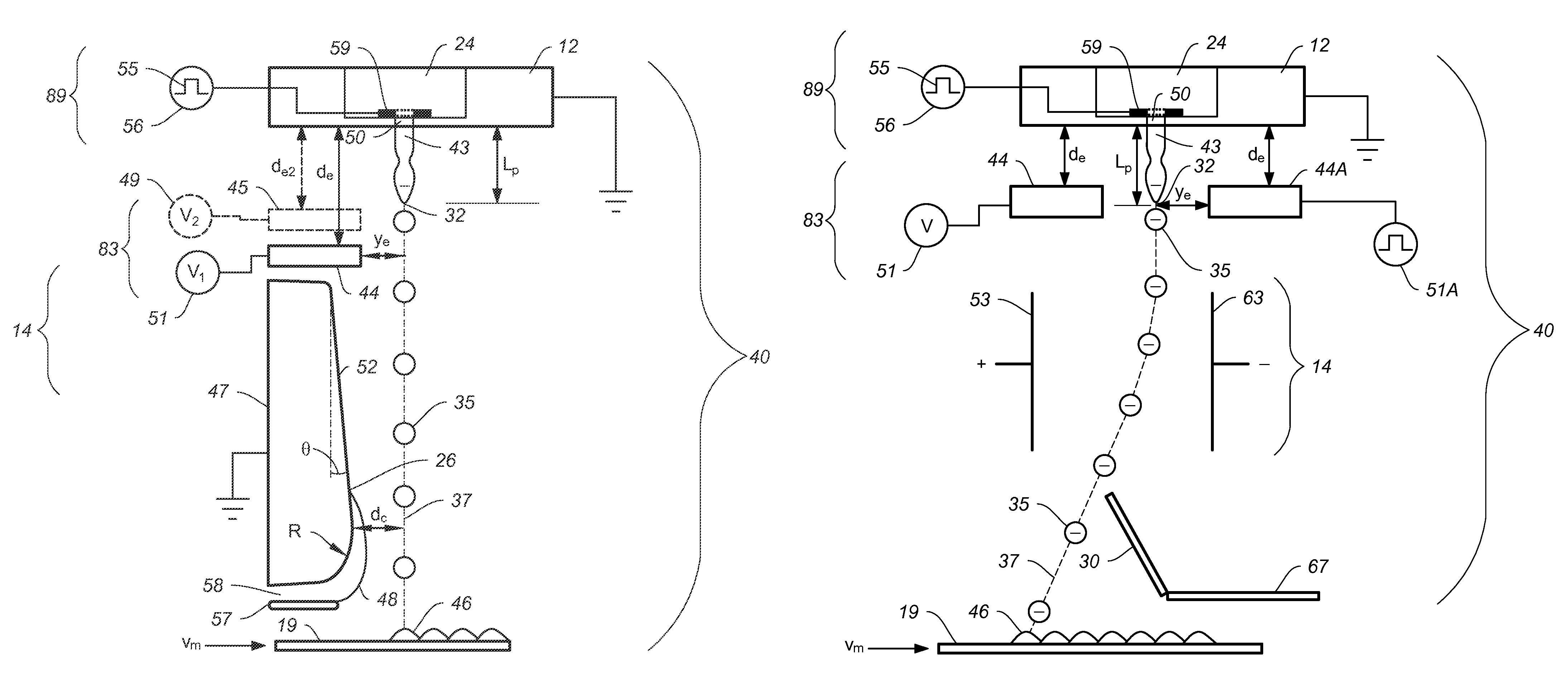
[0069]In order to selectively print drops onto a substrate, catchers are utilized to intercept non-print drops 36 which can then be sent to the ink recycling unit 15. FIGS. 4A-4C show a first embodiment in which a grounded catcher 47 positioned below the charge electrode 44 intercepts drops traveling along the non-print drop path 38 while allowing print drops 35 traveling down the print drop path 37 to contact the recording media 19 and be printed. In the embodiments shown in FIGS. 4A-4C the non-print drops are highly charged, deflected, captured by catcher 47 and recycled, while the print drops have a relatively low charge and are relatively undeflected and are printed on recording media 19. In FIG. 4A the breakoff length 32 of print drops 35 is Lp which is less than the charge electrode 44 to nozzle plane distance de so that a relatively low amount of charge is transferred to the print drops 35 as they break off. The print drops are not deflected by the grounded catcher 47 and the...

second embodiment

[0074]FIGS. 5A-5C shows cross sectional viewpoints through a liquid jet of this invention in which relatively non-deflected non-print drops 36 are collected by catcher 67 while deflected print drops 35 are allowed to pass by the catcher and be printed on recording media 19. In this embodiment print drops 35 are highly charged and deflected away from a catcher 67 as they travel along print drop path 37 allowing the print drops 35 to contact a recording media 19 and be printed. In this case the catcher 67 intercepts less charged non-print drops 36 traveling along the relatively undeflected non-print drop path 38. FIG. 5A shows a sequence of drops being generated in all print condition while printing at the maximum recording media speed, FIG. 5B shows a sequence of drops being generated in a no print condition and FIG. 5C shows a sequence of drops being generated in a normal print condition in which some of the drops are printed and some of the drops are not printed. As shown in FIG. 5...


PUM


Abstract

Drop formation devices are provided with drop formation waveforms to modulate liquid jets to cause portions of the liquid jets to form print drops having a jet breakoff length Lp in a print drop breakoff length range Rp and non-print drops having a jet breakoff length Lnp in a non-print drop breakoff length range Rnp. A timing delay device shifts the timing of the waveforms supplied to drop formation devices of first and second nozzle groups so that print drops formed from first and second nozzle groups are not aligned relative to each other. A charging device includes a charge electrode that is positioned relative to the breakoff length Lp and breakoff length Lnp such that there is a difference in electric field strength at the two breakoff lengths to produce a print drop charge state on print drops and a non-print drop charge state on non-print drops.

Description

CROSS REFERENCE TO RELATED APPLICATIONS[0001]Reference is made to commonly-assigned, U.S. patent application Ser. No. 13 / 115,434, entitled “EJECTING LIQUID USING DROP CHARGE AND MASS”, Ser. No. 13 / 115,465, entitled “LIQUID EJECTION SYSTEM INCLUDING DROP VELOCITY MODULATION”, Ser. No. 13 / 115,482, entitled “LIQUID EJECTION METHOD USING DROP VELOCITY MODULATION”, and Ser. No. 13 / 115,421, entitled “LIQUID EJECTION USING DROP CHARGE AND MASS”, the disclosures of which are incorporated by reference herein in their entirety.[0002]Reference is also made to commonly-assigned, U.S. patent application Ser. No. 13 / 424,436, entitled “DROP PLACEMENT ERROR REDUCTION IN ELECTROSTATIC PRINTER”, the disclosure of which is incorporated by reference herein in its entirety.FIELD OF THE INVENTION[0003]This invention relates generally to the field of digitally controlled printing systems, and in particular to continuous printing systems in which a liquid stream breaks into drops some of which are electros...

Claims


Application Information

Patent Timeline
Patent Type & Authority Patents(United States)
IPC IPC(8): B41J2/07
CPCB41J2/185B41J2/085B41J2002/1853B41J2002/032B41J2/09B41J2/03
Inventor MARCUS, MICHAEL A.PANCHAWAGH, HRISHIKESH V.ADIGA, SHASHISHEKAR P.
Owner EASTMAN KODAK CO
Why Eureka
Try Eureka