Mounting system for solar panels, and mounting rail and anchoring device therefor

Inactive Publication Date: 2012-12-27
RENUSOL
View PDF0 Cites 27 Cited by
  • Summary
  • Abstract
  • Description
  • Claims
  • Application Information

AI Technical Summary

Benefits of technology

[0008]According to one aspect, the present invention provides a mounting system for mounting one or more solar panels on a support structure, such as a roof structure, the system comprising: a plurality of elongate mounting members adapted to be arranged and secured spaced apart and substantially parallel to one another, each of the mounting members being adapted to receive and support an edge region of a solar panel such that each solar panel extends between at least two of the mounting members; and a plurality of anchoring devices for securing each of the mounting members to the support structure, with each of the anchoring devices comprising a footing to be rigidly fastened to the support structure and a coupling member for connection with a respective one of the mounting members. According to the invention, a spacing between the coupling member and the footing is selectively va

Problems solved by technology

Roof structures are particularly convenient for this purpose as they present a large surface area directed towards the sun, which is both out of the way and often largely out of view from the normal visual perspective, thereby rendering the installations relatively unobtrusive.
Many roof structures, however, are not horizontal but rather are pitched or angled, and thereby present significant challenges for the workers installing the solar panel array.
Thus, in addition to the fact that the framele

Method used


Image

  • Mounting system for solar panels, and mounting rail and anchoring device therefor
  • Mounting system for solar panels, and mounting rail and anchoring device therefor
  • Mounting system for solar panels, and mounting rail and anchoring device therefor

Examples


Example

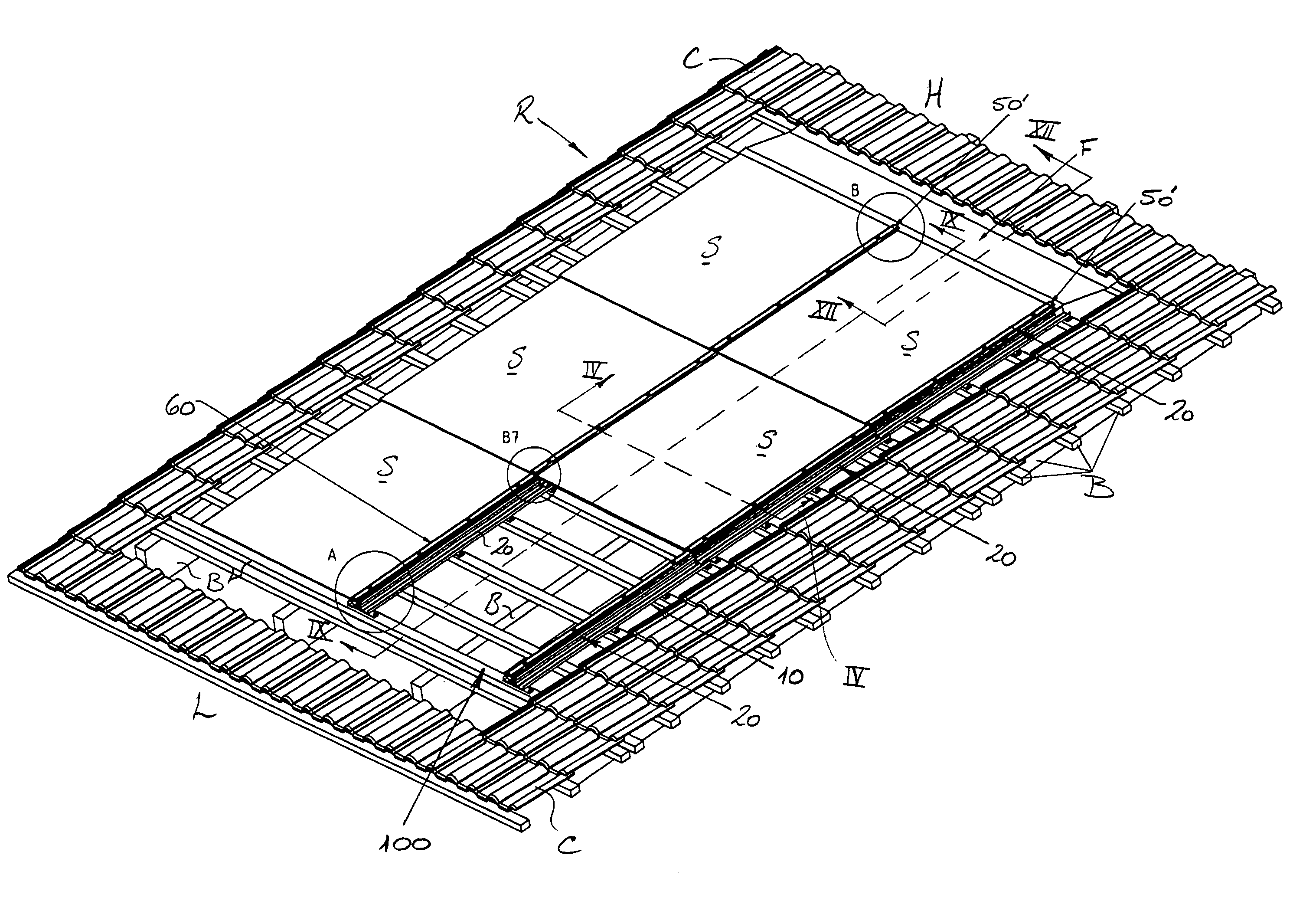
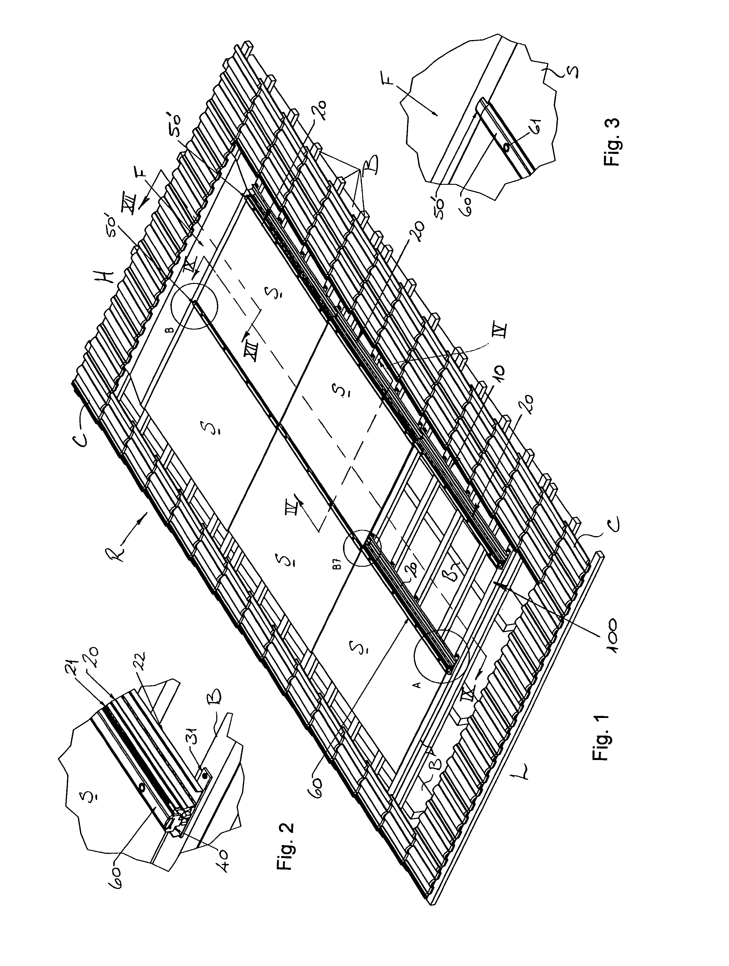
[0050]With reference to FIG. 1 of the drawings, a mounting system 100 according to a preferred embodiment of the invention is illustrated in an assembled state installed on a rooftop R. The mounting system 100 shown in FIG. 1 has been designed to carry six rectangular solar panels S securely fixed to a mounting frame 10 of the mounting system in a rectangular array. Five of the solar panels S are shown mounted on the mounting frame 10 and one is absent to reveal parts of the underlying mounting system 100, which will now be described in more detail. The solar panels S in this embodiment comprise relatively thin glass photovoltaic panels or modules having a frameless sheet-glass covering. It will be appreciated, however, that other types of solar panels may also be contemplated for use in the mounting system 100 of the invention. The solar panels S are rectangular and typically present a collecting surface with an area in the range of about 0.5 m2 to about 4 m2, although the area and...


PUM


Abstract

In one broad aspect, the present invention provides a mounting system (100) for mounting one or more solar panels (S), comprising: a plurality of elongate mounting members (20) adapted to be arranged and secured spaced apart and substantially parallel to one another; and a plurality of anchoring devices (30) for securing each of the mounting members (20) to a support structure, such as a roof structure. Each of the mounting members (20) is adapted to receive and support an edge region (E) of a solar panel (S), such that each solar panel (S) extends between at least two mounting members (20). Furthermore, each anchoring device (30) comprises a footing (31) to be rigidly fastened to the support structure, and a coupling member (35) for connection with a respective one of the mounting members (20). A spacing between the coupling member (35) and the footing (31) is selectively variable by a user to adjust and/or set an elevation (X) of the respective mounting member (20) relative to the support structure. In a related aspect, the invention provides a mounting rail (20) for the mounting system (100). In another related aspect, the invention also provides an anchoring device (30) for the mounting system (100).

Description

TECHNICAL FIELD[0001]The present invention relates to a mounting system for mounting solar panels, as well as to a mounting rail and an anchoring device designed for use in the mounting system of the invention.[0002]The mounting system of the invention and, of course, the associated mounting rail and the anchoring device are particularly suitable for use in mounting solar panels on a rooftop, such as a pitched rooftop, or similar structure, and it will convenient to describe the invention in this exemplary context. It is to be appreciated, however, that the mounting system of the invention is not limited to use on rooftops or sloping surfaces, but may also be employed where the solar panels are to be mounted on any of a variety of supporting frameworks.BACKGROUND OF THE INVENTION[0003]As a result of the increasing trend towards adoption of renewable energy sources, the installation of solar panel arrays is gaining in popularity, not only for industrial and institutional applications...

Claims


Application Information

Patent Timeline
IPC IPC(8): F24J2/52
CPCF24J2/4614F24J2/5207F24J2/5245F24J2/5258F24J2/5264Y02E10/47F24J2002/467F24J2002/5222F24J2002/5273Y02B10/20F24J2002/0061F24S25/35F24S25/61F24S25/636F24S25/70F24S40/44F24S2020/13F24S2025/01F24S2025/6007F24S2025/805
Inventor KUBSCH, MICHAELZSCHOCH, STEFANWENZLAFF, JANRADISCHAT, UWE
Owner RENUSOL
Why Eureka
Try Eureka