Disc brake apparatus
- Summary
- Abstract
- Description
- Claims
- Application Information
AI Technical Summary
Benefits of technology
Problems solved by technology
Method used
Image

Examples
first embodiment
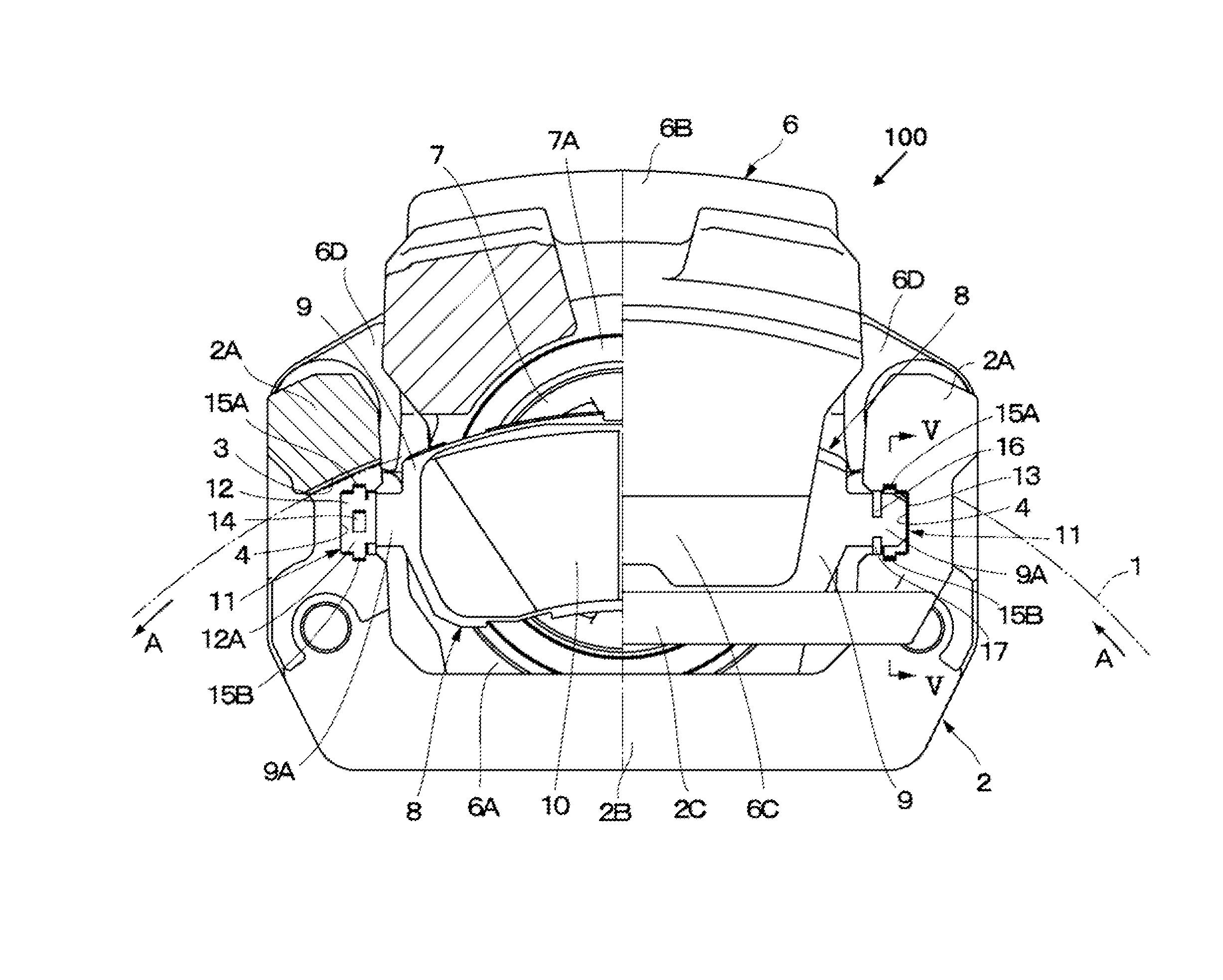
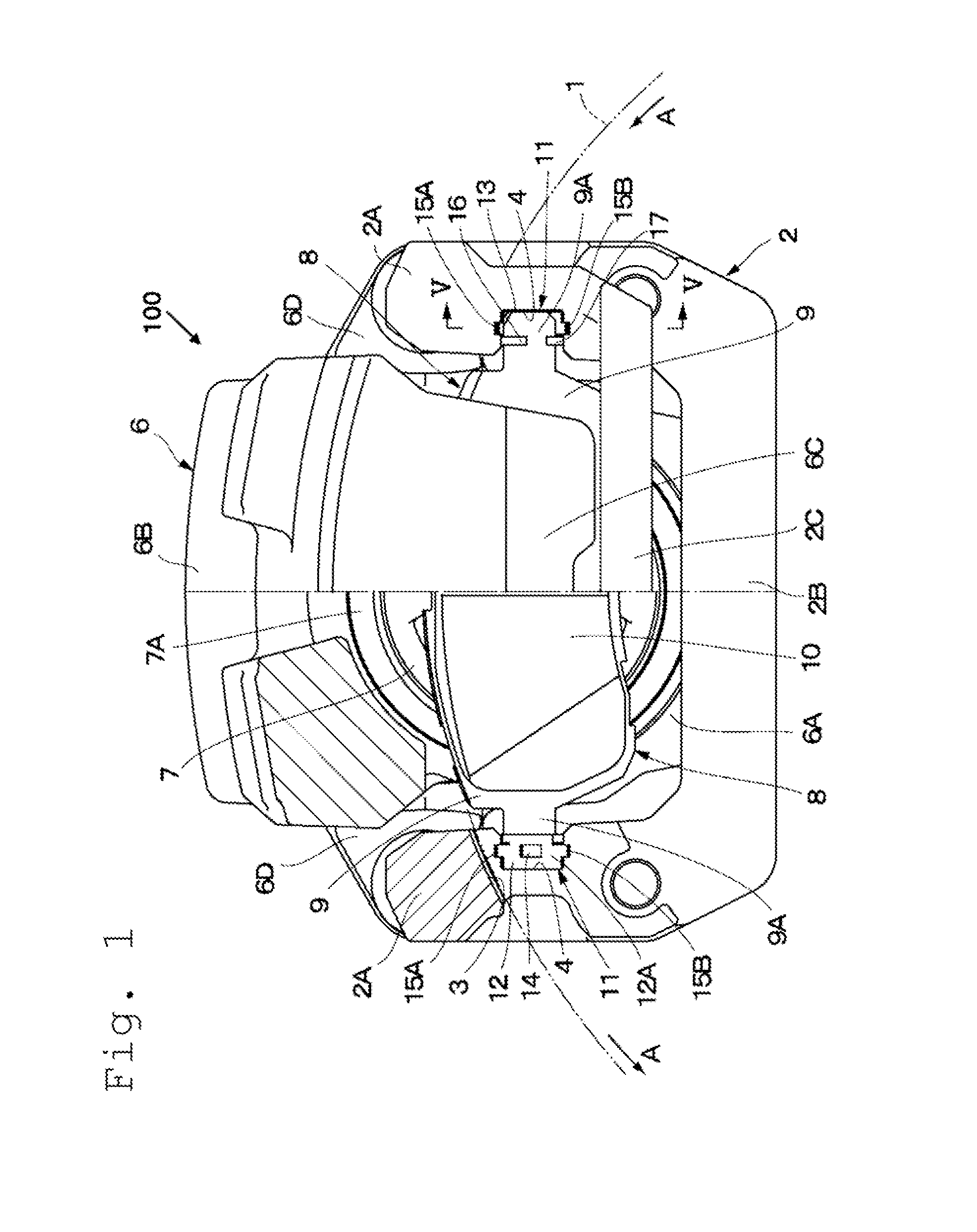
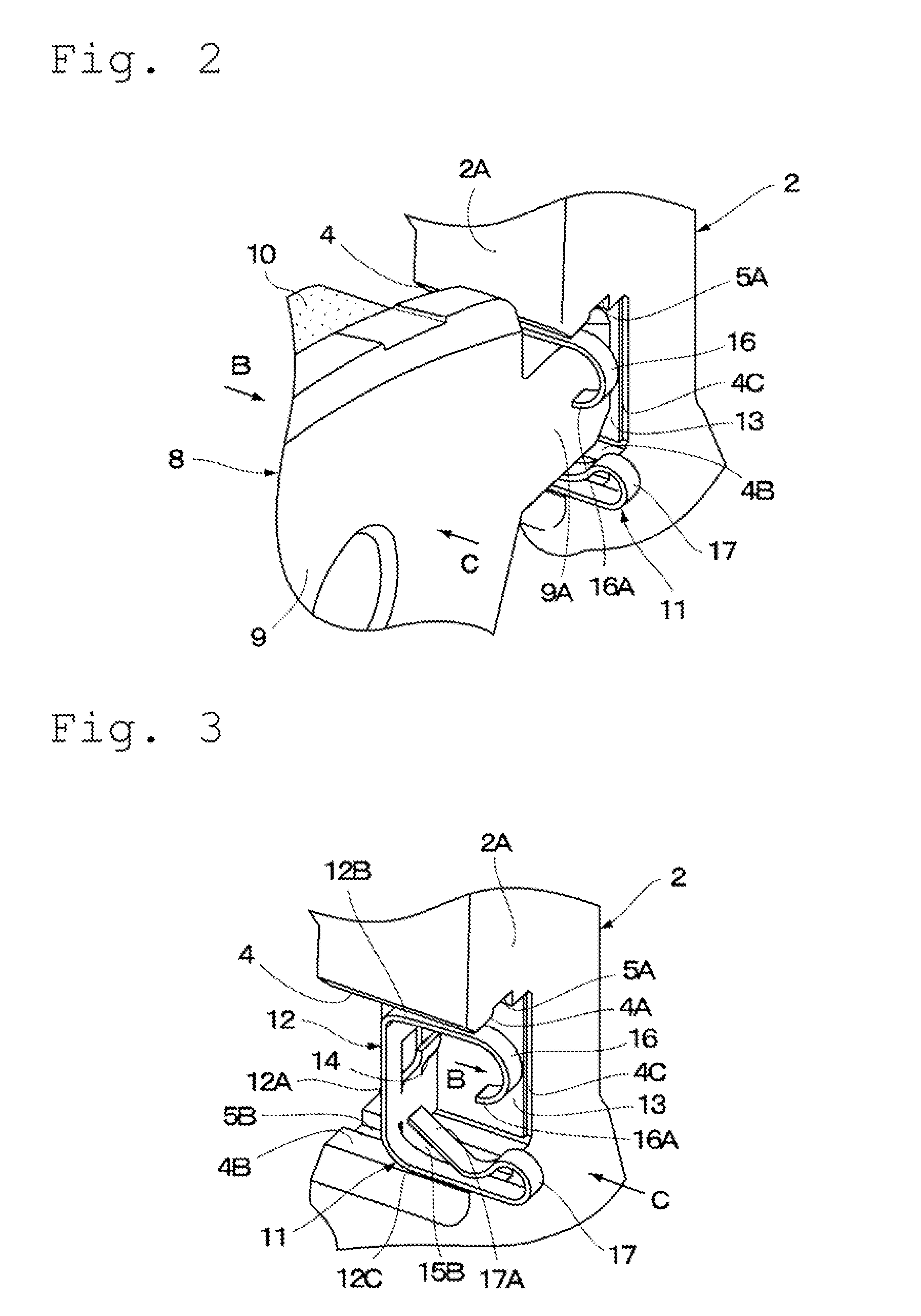
[0036]FIGS. 1 to 8 illustrate a disc brake apparatus according to a In description of this embodiment, a floating-type disc brake apparatus is taken as an example. However, the present invention is applicable also to what is called an opposed-type disc brake apparatus, in which a caliper having a cylinder and a piston respectively provided on both sides of a disc rotor so as to oppose each other is fixed to a non-rotating portion of a vehicle. In FIG. 1, a disc rotor 1, which is rotatable, is illustrated. The disc rotor 1 rotates, for example, in a direction indicated by the arrows A illustrated in FIG. 1 together with wheels (not shown) when a vehicle runs forward and rotates in the direction opposite to the direction indicated by the arrows A when the vehicle moves backward.
[0037]A caliper 100 is a floating-type caliper as an example of a caliper according to the present invention, and includes a mounting member 2 and a caliper main body 6 which is slidably provided to the mounti...
third embodiment
[0096]Specifically, the biasing member 31 used in the third embodiment is provided between the arm 2A (pad guide 4), which is located, for example, on the disc-incoming side, of the two arms 2A of the mounting member 2, illustrated in FIG. 1, and a corresponding one of the ear portions 9A of the friction pads 8. In this manner, the biasing member 31 on the disc-incoming side constantly biases one of the ear portions 9A of each of the friction pads 8, which is located on the disc-incoming side, toward the disc-outgoing side of the disc rotor 1 (in the direction indicated by the arrow A illustrated in FIG. 1) with a weak force by the circumferential spring part 35A provided to the far-side plate portion 35. Then, each of the ear portions 9A located on the disc-outgoing side of the disc rotor 1 is elastically pressed against the ear-side wall surface 4C of the pad guide 4 by a biasing force of the circumferential spring part 35A.
second embodiment
[0097]In this case, for example, the biasing member 21 described in the second embodiment and illustrated in FIGS. 9 and 10 may be provided between the arm 2A (pad guide 4) of the two arms 2A of the mounting member 2, which is located on the disc-outgoing side, and a corresponding one of the ear portions 9A of the friction pads 8. Moreover, a biasing member, which is approximately similar to the biasing member 31 except that the circumferential spring part 35A is not provided to the far-side plate portion 35, may be provided.
[0098]The pad-return portion 36 serving as the first spring part is extended integrally from an end of the upper concave-portion facing plate portion 34A of the main body portion 32 of the biasing member 31, which is on the side opposite to an abutment-plate portion 37 through an upper claw portion 38A described below therebetween. The pad-return portion 36 is formed at a distal end of the concave-portion facing plate portion 34A so as to be bent at an angle inw...
PUM
 Abstract
Description
Claims
Application Information
 - R&D
- Intellectual Property
- Life Sciences
- Materials
- Tech Scout
- Unparalleled Data Quality
- Higher Quality Content
- 60% Fewer Hallucinations
Browse by: Latest US Patents, China's latest patents, Technical Efficacy Thesaurus, Application Domain, Technology Topic, Popular Technical Reports.
© 2025 PatSnap. All rights reserved.Legal|Privacy policy|Modern Slavery Act Transparency Statement|Sitemap|About US| Contact US: help@patsnap.com