Vehicle drive apparatus

Active Publication Date: 2013-01-10
AISIN AW CO LTD +1
View PDF3 Cites 9 Cited by
  • Summary
  • Abstract
  • Description
  • Claims
  • Application Information

AI Technical Summary

Benefits of technology

[0031]This makes it possible to prevent the axial dimension of the drive apparatus from increasing as a result of providing the locking mechanism and the centering mechanism. Especially when the locking mechanism is disposed outside the bearing for the rotor shaft of the motor generator and on the inner diameter side of the coil end, the axial dimen

Problems solved by technology

However, when the ring gear is fixed to the case on the outer periphery of the ring gear, this fixing disables alignment through meshing between the ring gear and the pinion gear.
Machining the inner surface of the case is, however, difficult (it is technically possible, but becomes highly expensive).
Specifically, when the ring gear is fixed, if the ring gear is fixed to the case on the outer periphery of the ring gear, achieving good axis accuracy of the ring gear is practically difficult.
The aggravated axis accuracy of the

Method used


Image

  • Vehicle drive apparatus
  • Vehicle drive apparatus
  • Vehicle drive apparatus

Examples


Example

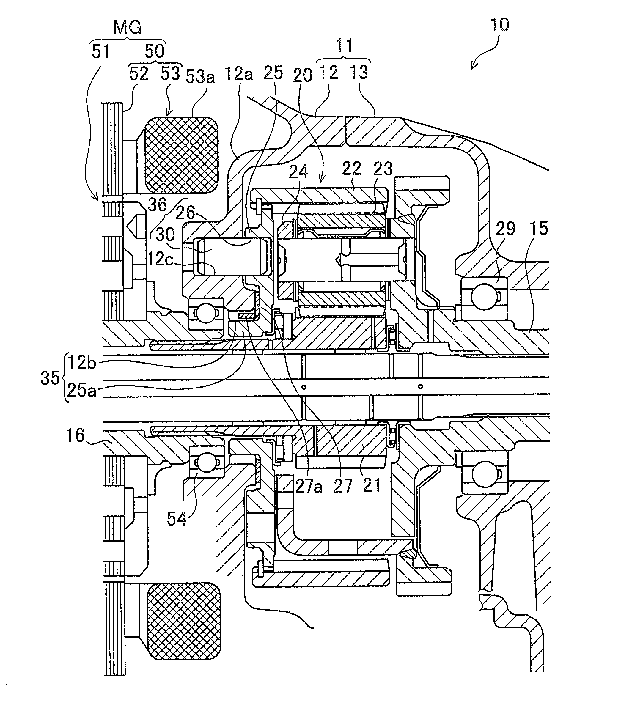
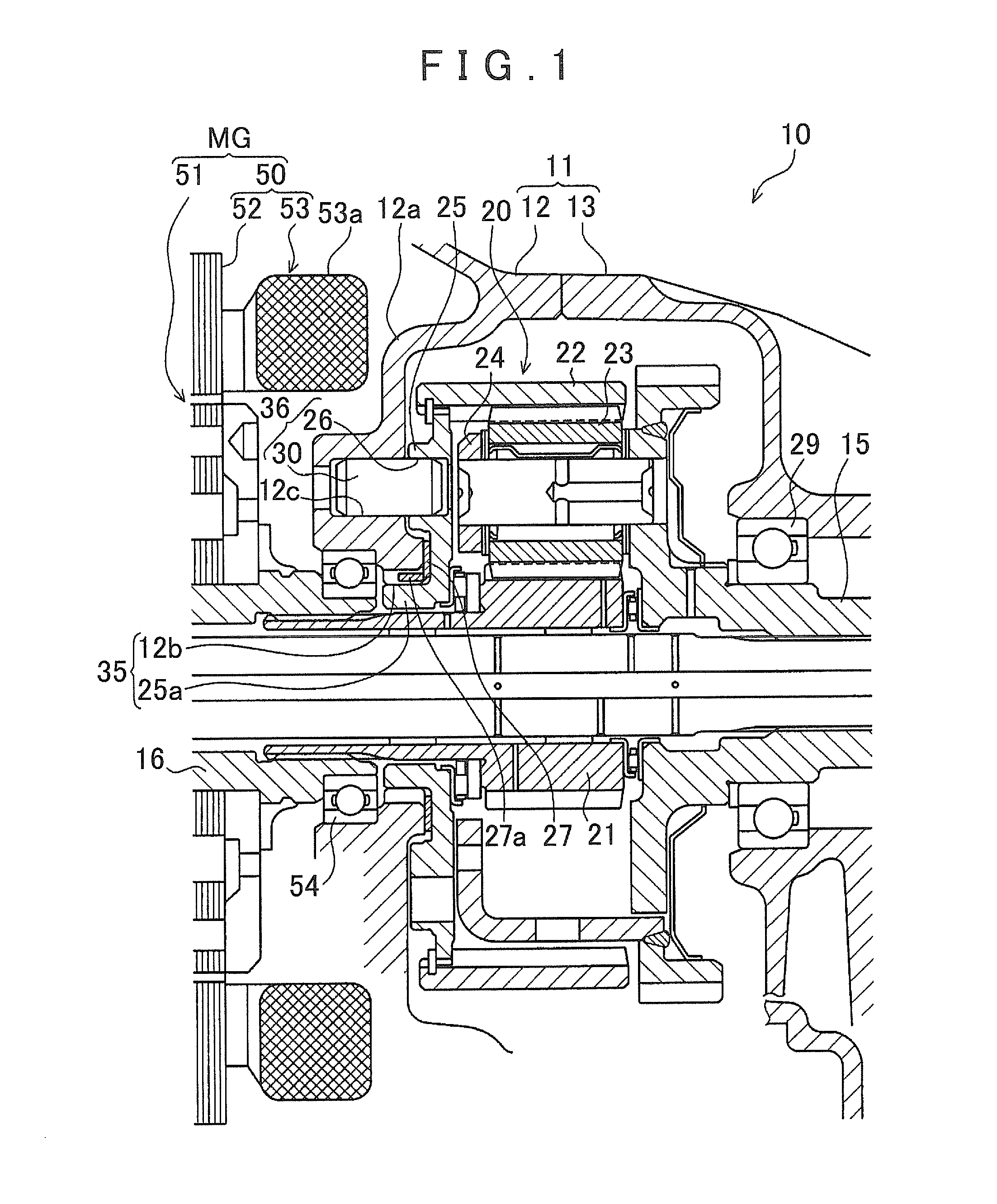
[0040]A vehicle drive apparatus according to a preferred embodiment of the present invention will be described in detail below with reference to the accompanying drawings. The embodiment represents a drive apparatus disposed longitudinally in a front-engine rear-drive (FR) hybrid vehicle. The drive apparatus according to the embodiment will be described with reference to FIG. 1. FIG. 1 is a cross-sectional view schematically showing a configuration of a speed reduction mechanism of the drive apparatus according to the embodiment.

[0041]Referring to FIG. 1, a drive apparatus 10 according to the embodiment includes a motor generator MG, a speed reduction mechanism 20 connected to the motor generator MG, and an output shaft 15 connected to the speed reduction mechanism 20. These are accommodated inside a transmission case 11 composed of a main housing 12 and an extension housing 13. The main housing 12 and the extension housing 13 each are formed of a metallic material, such as aluminum...


PUM


Abstract

A vehicle drive apparatus includes a motor generator, a speed reduction mechanism connected to a rotor shaft of the motor generator, an output shaft connected to the speed reduction mechanism, an intermediate wall separating the motor generator from the speed reduction mechanism, and a bearing that is fixed to the intermediate wall and supports the rotor shaft. The motor generator, intermediate wall, speed reduction mechanism, and output shaft are disposed in this order, and a ring gear of the speed reduction mechanism is fixed. The ring gear is fixed to the intermediate wall via a ring gear flange that is positioned relative and fixed to the intermediate wall by a centering mechanism and a locking mechanism. The centering mechanism is formed by fitting a boss of the ring gear flange and the intermediate wall. The locking mechanism is disposed on an outer peripheral side relative to the centering mechanism.

Description

INCORPORATION BY REFERENCE[0001]The disclosure of Japanese Patent Application No. 2010-081557 filed on Mar. 31, 2010 including the specification, drawings and abstract is incorporated herein by reference in its entirety.BACKGROUND OF THE INVENTION[0002]The present invention relates to a vehicle drive apparatus that outputs rotation of a motor generator from an output shaft by reducing a speed of the rotation through a speed reduction mechanism, and more specifically, to a vehicle drive apparatus including a ring gear fixed in a speed reduction mechanism.DESCRIPTION OF THE RELATED ART[0003]A known vehicle including a motor generator as a drive source (for example, a hybrid vehicle and an electric vehicle) includes a speed reduction mechanism that transmits rotation of the motor generator to an output shaft by reducing the speed of the rotation. The speed reduction mechanism includes a sun gear, a carrier, and a ring gear. Of these components, either the carrier or the ring gear needs...

Claims


Application Information

Patent Timeline
IPC IPC(8): F16H1/10F16H57/04F16H57/00
CPCB60K6/48F16H1/227F16H57/0006F16H57/0476F16H57/0479Y10T74/19684F16H57/08H02K7/083H02K7/116Y02T10/6221F16H57/0482B60K2006/4825B60K2006/4833Y02T10/62
Inventor MORI, ATSUSHIKUBO, RYOHEISHINTANI, HIROKITAKASU, KOJISUZUKI, HARUHISANISHIGAYA, MASABUMI
Owner AISIN AW CO LTD
Why Eureka
Try Eureka