Micro-speaker

a microphone and microphone technology, applied in the field of microphones, can solve the problems of unbalanced vibration of the diaphragm, wire breakage,

Inactive Publication Date: 2013-01-17
AAC TECH PTE LTD +1
View PDF8 Cites 63 Cited by
  • Summary
  • Abstract
  • Description
  • Claims
  • Application Information

AI Technical Summary

Problems solved by technology

As the result, the leading wires will be broken.
In another hands, only one end of the voice coil is fixed by the diaphra

Method used


Image

  • Micro-speaker
  • Micro-speaker
  • Micro-speaker

Examples


Embodiment Construction

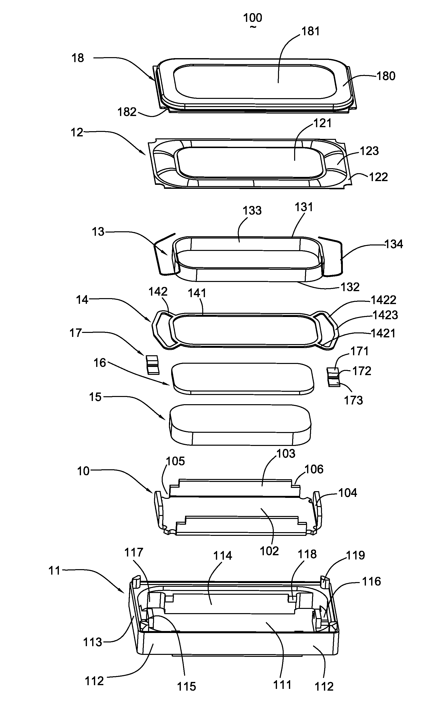
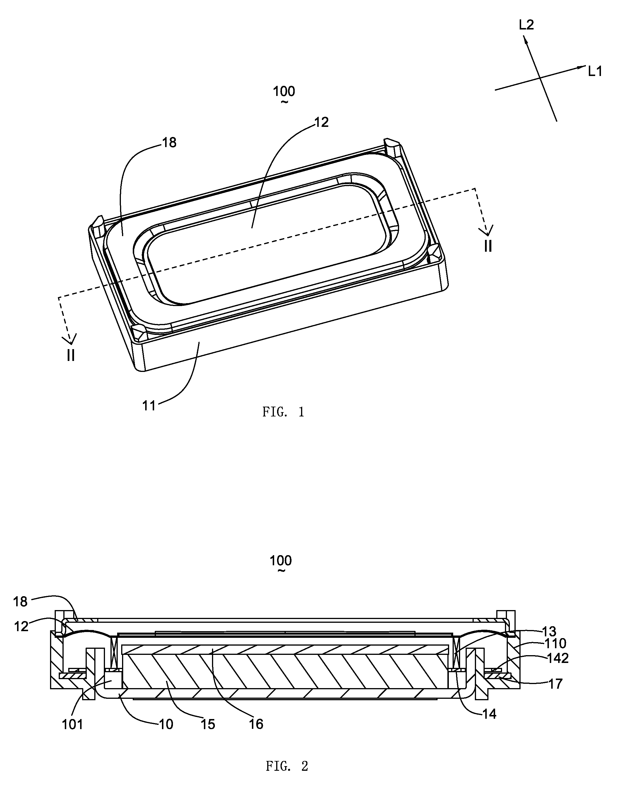
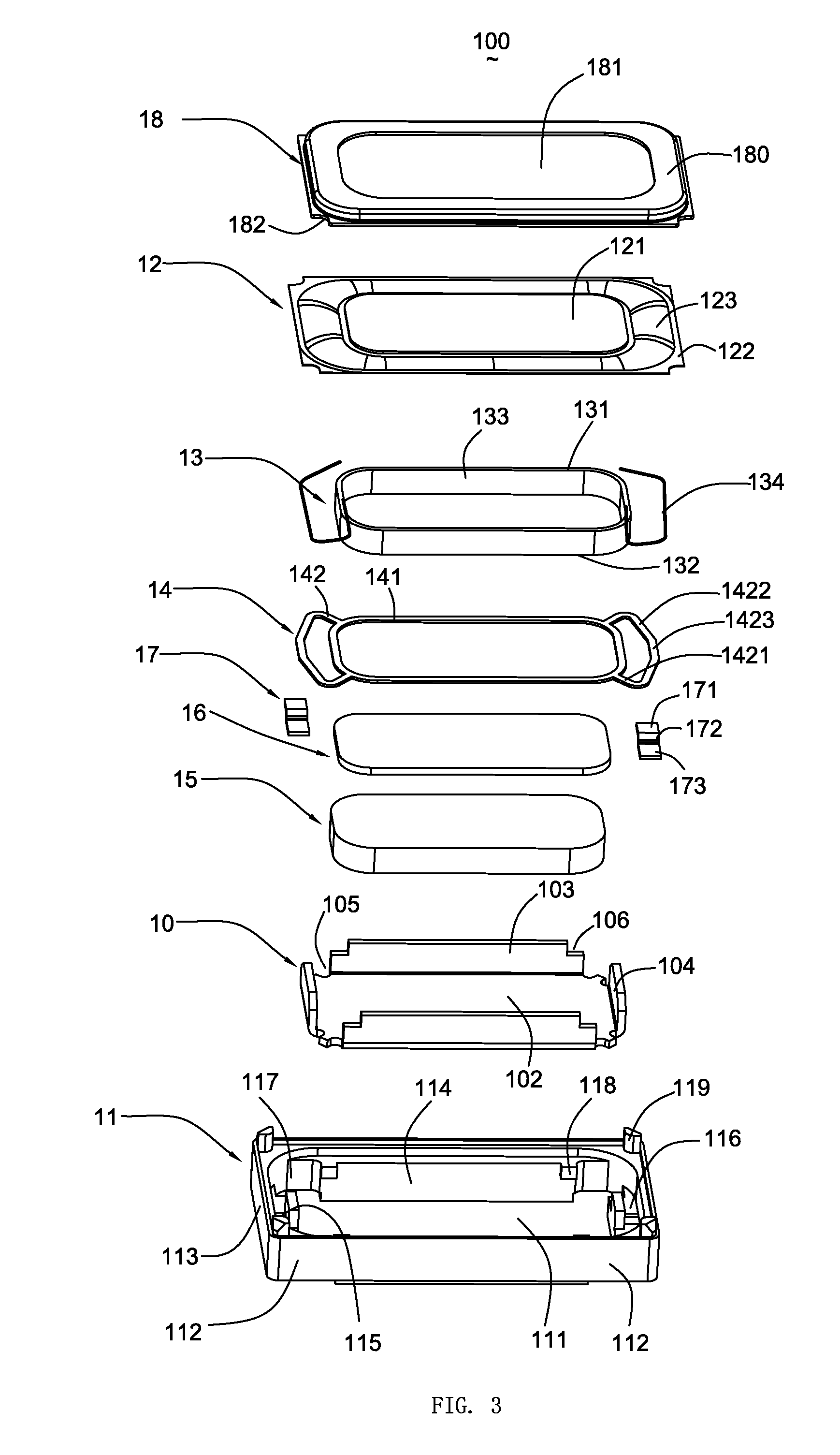
[0012]Referring to FIGS. 1-3, a micro-speaker 100, according to a first exemplary embodiment, includes a frame 11, a diaphragm 12 mounted on the frame 11, a magnetic system received in the frame 11 and defining a magnetic gap 101, a voice coil 13 attached to the diaphragm 12 for driving the diaphragm 12 and suspended in the magnetic gap 101, a suspension 14 mounted on the frame 11 and assembled on the voice coil 13, a pair of contacts 17 coupled with the suspension 14 for providing electrical signals to the voice coil 13, and a case 18 covering a periphery of the diaphragm 12. The micro-speaker 100 has a longitudinal direction L1 and a lateral direction L2 perpendicular to the longitudinal direction L1.

[0013]Referring to FIGS. 2 and 3, the frame 11 includes a base portion 110 and a receiving room 111 surrounded by the base portion 110. The base portion 110 has a pair of longitudinal sidewalls 112, a pair of lateral sidewalls 113 connected with the adjacent longitudinal sidewalls 112...


PUM


Abstract

A micro-speaker includes a frame, a diaphragm mounted on the frame, a magnetic system received in the frame and defining a magnetic gap, a voice coil driving the diaphragm and suspended in the magnetic gap, and a suspension having a body portion and at least a pair of connecting portion extending from the body portion and mounted on the frame. The body portion of the suspension connects with the voice coil and far away from the diaphragm for cooperating with the diaphragm to fix the coil firmly, thereby ensuring the vibrating of the diaphragm is stable and balanced.

Description

FIELD OF THE INVENTION[0001]The present disclosure relates to the art of speakers and, particularly to a micro-speaker having a suspension attached on a coil.DESCRIPTION OF RELATED ART[0002]With the continuing development of audio and sound technology, micro-speakers have been widely used in electronic devices, such as cellular phones, PDAs (personal digital assistants), and so on.[0003]A micro-speaker related to the present invention includes a case having a sound hole, a frame attached to the case for forming a chamber together with the case, a magnetic circuit system received in the chamber and having a magnetic gap, a diaphragm mounted on the frame, and a voice coil attached to a lower surface of the diaphragm and suspended in the magnetic gap. The voice coil has a body attached to the lower surface of the diaphragm and a pair of leading wires drawn out from the body and suspended in the chamber. While electrified, the voice coil will be activated to vibrate by the electromagnet...

Claims


Application Information

Patent Timeline
IPC IPC(8): H04R1/00
CPCH04R9/043
Inventor HUANG, XING-ZHIXI, LI-ZHUZHANG, XIONG
Owner AAC TECH PTE LTD
Why Eureka
Try Eureka