Tracklaying gear

a technology of gear and damping layer, applied in the direction of hoisting equipment, mechanical equipment, transportation and packaging, etc., can solve the problem of silent operation noise, and achieve the effect of relieving the damping layer

Active Publication Date: 2013-01-24
JOSEPH VOEGELE AG
View PDF1 Cites 7 Cited by
  • Summary
  • Abstract
  • Description
  • Claims
  • Application Information

AI Technical Summary

Benefits of technology

[0015]The set object is achieved with the features of the present invention in which the drive chain wheel and / or the idler wheel is, between the axle and the caterpillar track, divided into inner and outer annular parts which are guided relatively to the axle and are exclusively movably radially relative to one another and so as to slide against each other. The at least two damping layers are arranged internally between the parts. Here, the damping layers take on loads exerted by the caterpillar track on the metallic parts of the drive chain wheel or the idler wheel, without, however, coming into direct contact with the caterpillar track. In this manner, an effective inner damping is achieved by consuming the energy from the essentially radially acting impacts in the damping layer with radial relative motions between the parts. Since the parts are guided to exclusively slide radially relative to one another, no impacts are transmitted via the sliding guide, but lateral guiding forces are built up. Impacts inevitably exerted by the caterpillar track in the driving operation are thus dampened by the integrated damping layers, whereby above all operating noise and also wear are reduced. However, the integration of the damping layers should be designed such that there is nevertheless a metallic contact also at least between the drive chain wheel and the caterpillar track in order not to overload the damping layers or to wear them down prematurely, and mainly to transmit lateral guiding forces. Despite the damping layers minimizing the operating noise, with the invention, shearing forces in the damping layers are avoided by the exclusively radial sliding guide, which will increase service life and ensure a stable, directed running of the caterpillar track over the wheels.
[0016]In one suitable embodiment, in the idler wheel and / or optionally in the drive chain wheel, in addition two annular damping layers with approximately identical diameters are provided axially outside and separated by a space in the axial direction, and in the region of the space, the metallic external teeth of the drive chain wheel or the guide collar of the idler wheel are arranged, so that here, mainly load transmission takes place, while the additional damping layers dampen abrupt energy peaks from impacts generated by the caterpillar track without being overloaded in the process, because the inner damping layers are also effective. The respective additional damping layer is attached outside on the respective bearing shoulder e.g. at the idler wheel, and firmly connected to it, preferably by drawing up, oversize shrink fitting, spraying, gluing or vulcanizing. While the raised guide collar transmits at least lateral guiding forces optionally in direct contact with the caterpillar track, impacts of the caterpillar track are also dampened by the additional damping layers which do not have to transmit the total load of the caterpillar track as would be the case with a solid rubber jacket of the idler wheel. This solution can lead to a very silent operating noise especially with the idler wheel.
[0018]In a suitable embodiment, the outer part of the drive chain wheel comprising the circumferential teeth and embodied as single-part ring disk or as ring disk assembled from segments with an internal circumferential base part and at least one first radial guiding structure, the inner part, which is preferably separable for assembly, is embodied with a circumferential crown matching the base part with at least one second radial guiding structure matching the first radial guiding structure, cylindrical or conical support surfaces facing each other are provided at the base part and at the crown, the respective damping layer is arranged between the support surfaces, optionally firmly connected to a support surface, and the first and the second radial guiding structures engage each other with a radial free motion. This embodiment of the drive chain wheel is structurally simple and fail-safe with the radial sliding guide.
[0020]Suitably, the crown is axially wider than the base part or the supporting ring, annular flanges radially projecting to the outside are provided at the edges of the crown which secure the base part or the supporting ring, respectively, in the axial direction without metallic contact because their protrusion is preferably smaller than the radial thickness of the damping layer. This also increases the lateral stiffness of the damping layers.
[0025]In a structurally simple embodiment, the first radial guiding structure has an annular flange projecting from the adjacent support surface to the inside with an approximately rectangular cross-section, and the second radial guiding structure comprises an annular groove, also with an approximately rectangular cross-section, which is recessed to the inside with respect to the support surface. A reversed structural shape is also possible, i.e. an annular flange gripping from the inner part to the outside and an annular groove immersed in the outer part. The annular flange is stably radially guided in the annular groove over a large surface and relieves the damping layer from possibly damaging flexing and shearing forces. Here, there can be direct metallic contact, or the guiding surfaces can comprise sliding or protecting coverings.

Problems solved by technology

This solution can lead to a very silent operating noise especially with the idler wheel.

Method used


Image

  • Tracklaying gear
  • Tracklaying gear
  • Tracklaying gear

Examples


Embodiment Construction

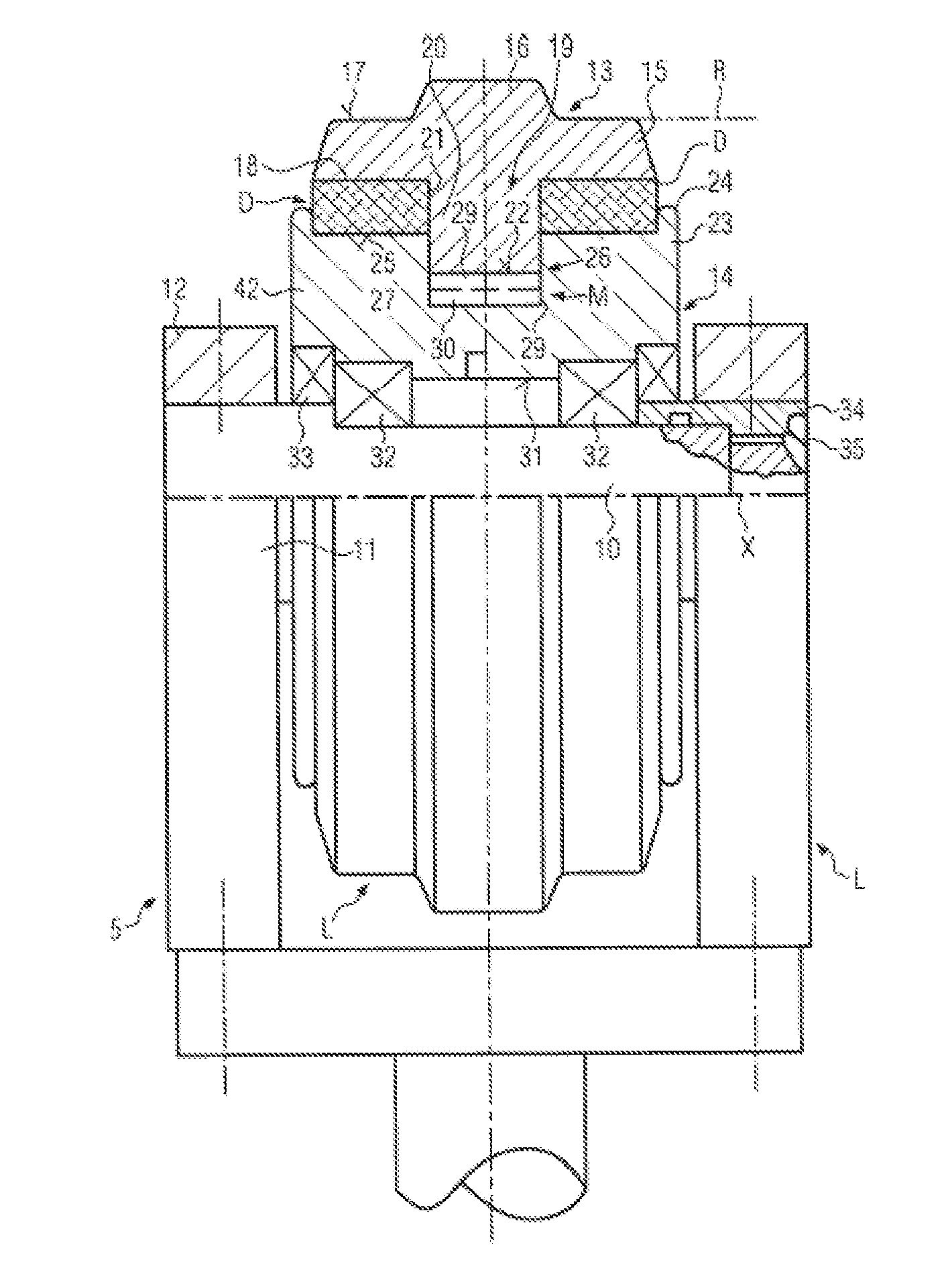
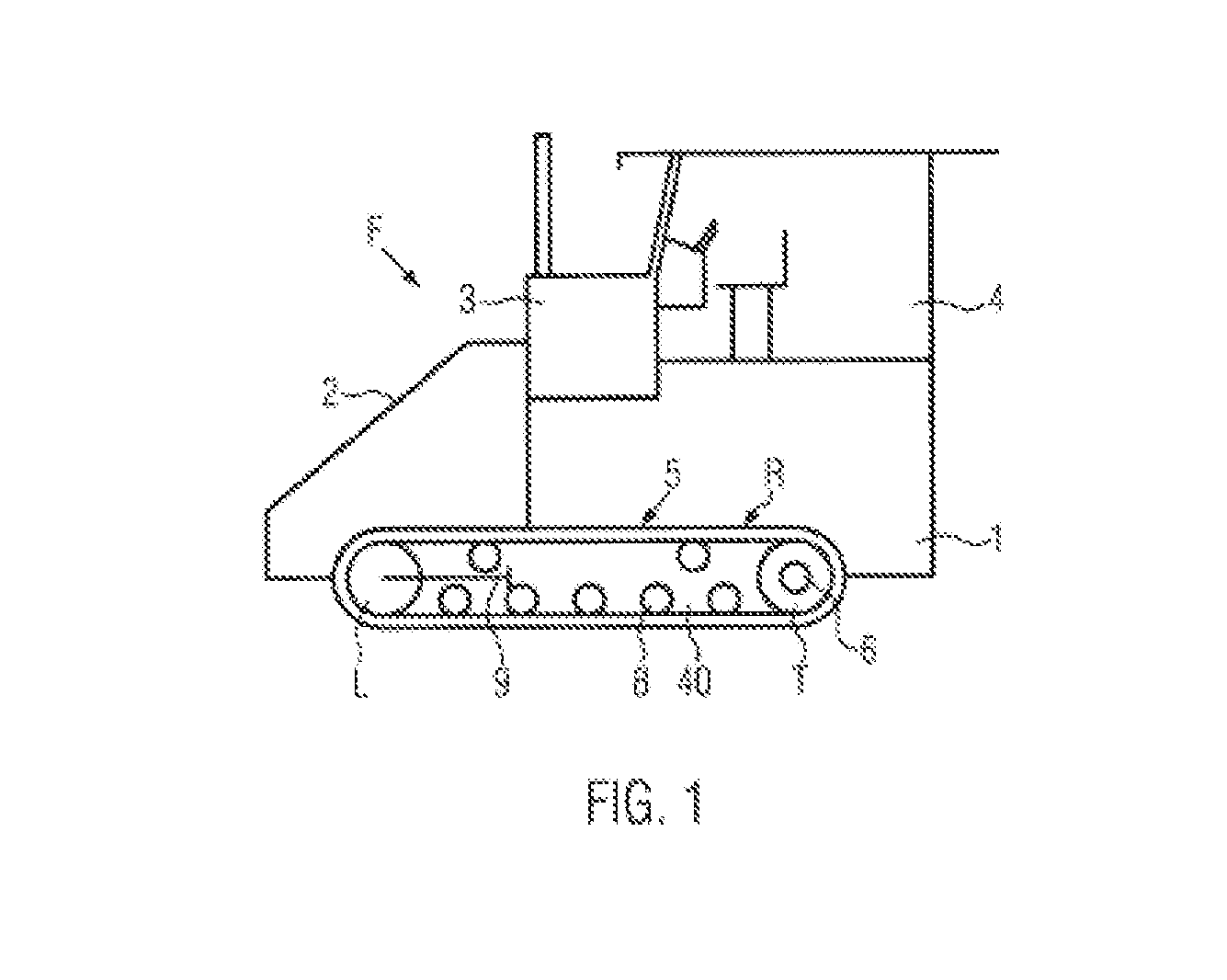
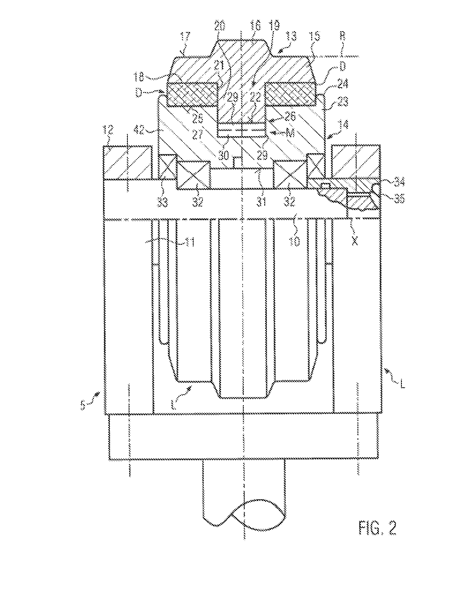
[0033]A road finishing machine or feeder F schematically shown in FIG. 1 comprises a chassis 1 with a front material bunker 2, an elevated primary power plant 3, for example a diesel engine with a non-depicted pump transfer gear for hydraulically actuated working components, behind it a driver stand 4 and at the bottom side a tracklaying gear 5 on either side. The tracklaying gear 5 contains a drive chain wheel T (tumbler), for example driven by a hydrostat 6, as well as an idler wheel L, which are placed, together with support rollers 8, at a supporting structure 40 and in a caterpillar track R and connected to the chassis 1 via a non-depicted suspension. The idler wheel L is acted upon by a tensioning device 9 to keep the caterpillar track R under the required operating tension (see also FIG. 5).

[0034]In the operation of the tracklaying gear 5 e.g. of FIG. 1, according to FIG. 5, a polygon effect occurs in which the caterpillar track R (direction of motion F) cyclically exerts, in...


PUM


Abstract

In a tracklaying gear of a road finishing machine or a feeder with a drive chain wheel comprising circumferential teeth and being rotatably driven about an axis, and at least one idler wheel freely rotating about an axis inside a caterpillar track damping layers having damping material and exclusively radial sliding guides are integrated in the drive chain wheel and / or the idler wheel between the axis and the caterpillar track.

Description

FIELD OF THE INVENTION[0001]The invention relates to a tracklaying gear of a road finishing machine or a feeder with a drive chain wheel having circumferential teeth and wherein the wheel is rotatably driven about an axis.BACKGROUND OF THE INVENTION[0002]The idler wheel of a generic tracklaying gear disclosed in WO 03 / 018388 A comprises an outer part with a U-shaped cross-section consisting of individual segments, and an inner part mounted to be rotatable about the axis which engages, with a thickened outer rim, the U-groove of the outer part from the inside. Each segment is movably fixed in the thickened rim via two axial pins. On both sides of a centric surrounding collar at the outer side of the rim, elastomer rings of an approximately rectangular cross-section are inserted with pre-tension and relatively movably support the outer part on the inner part with a radial as well as an axial clearance on both sides. Due to the pre-tension of the elastic rings, these have load-transmit...

Claims


Application Information

Patent Timeline
Patent Type & Authority Applications(United States)
IPC IPC(8): B62D55/12
CPCB62D55/0966B62D55/0963
Inventor BRAUN, ARTHUR
Owner JOSEPH VOEGELE AG
Why Eureka
Try Eureka