Eureka AIR delivers breakthrough ideas for toughest innovation challenges, trusted by R&D personnel around the world.

Electromechanical Switch for Controlling Toxic Gas

a technology of electronic switch and toxic gas, which is applied in the direction of fire alarms, instruments, lighting and heating apparatus, etc., can solve the problems of carbon monoxide poisoning, no longer available hemoglobin for transporting oxygen, headaches, nausea,

Inactive Publication Date: 2013-01-24
MAF TECH
View PDF4 Cites 13 Cited by
  • Summary
  • Abstract
  • Description
  • Claims
  • Application Information

AI Technical Summary

Benefits of technology

The patent text describes safety systems that can detect toxic gases and prevent them from being released into the environment. The systems use an interrupt device that detects the toxic gas and activates a circuit that allows the engine or toxic gas detector to start. The interrupt device includes a detector circuit and a permitting circuit that allows the engine or toxic gas supply to operate if the safety system is healthy and functioning properly. The technical effect of these safety systems is to provide a safer way to handle toxic gases, reducing the risk of accidental releases and minimizing the impact on the environment.

Problems solved by technology

If this gas is not ventilated properly, carbon monoxide poisoning may result.
Once combined with the hemoglobin, the hemoglobin is no longer available for transporting oxygen.
Because it takes several hours to remove carbon monoxide from the body of a person, concentrations of carbon monoxide can gradually build up in the blood causing headaches, fatigue, dizziness, nausea, burning eyes, or unconsciousness.
Incomplete oxidation during combustion in gas ranges and non-vented gas or kerosene heaters may cause high concentrations of CO in indoor air.
Worn or poorly adjusted and maintained combustion devices (e.g., boilers, furnaces) can be significant sources of CO.
However, CO detectors / alarms always have been and still are designed to alarm before potentially life-threatening levels of CO are reached.
Because carbon monoxide is a colorless, odorless, tasteless gas, it virtually impossible to detect its presence without a carbon monoxide detector.
Until recently, the cost of these cells and concerns about their long term reliability had limited uptake of this technology in the marketplace although these concerns are now largely overcome.
This sensor is more expensive and less used in residential CO detectors.

Method used


Image

  • Electromechanical Switch for Controlling Toxic Gas
  • Electromechanical Switch for Controlling Toxic Gas
  • Electromechanical Switch for Controlling Toxic Gas

Examples


Embodiment Construction

[0041]There are reported and existing cases of people improperly operating power generators indoors without proper ventilation, which resulted in fatalities. A method and device to detect dangerous levels of CO and effectively shutdown the gas engine was developed, tested and successfully installed in portable power generators which will remedy this situation.

[0042]Embodiments of the invention use a variety of methods to interface to the gas engine without interfering with its normal operation, and without modifications to the engine, or alternator. This system monitors the emission of CO in the vicinity of the power generator. Once it detects dangerous concentrations of CO, it effectively shuts down the engine. The engine cannot be restarted until the level of CO drops down. The preferred embodiment has the capability of minimizing false shutdowns. Many scenarios were properly considered to encompass normal operational ways of the power generators, while contemplating and understan...

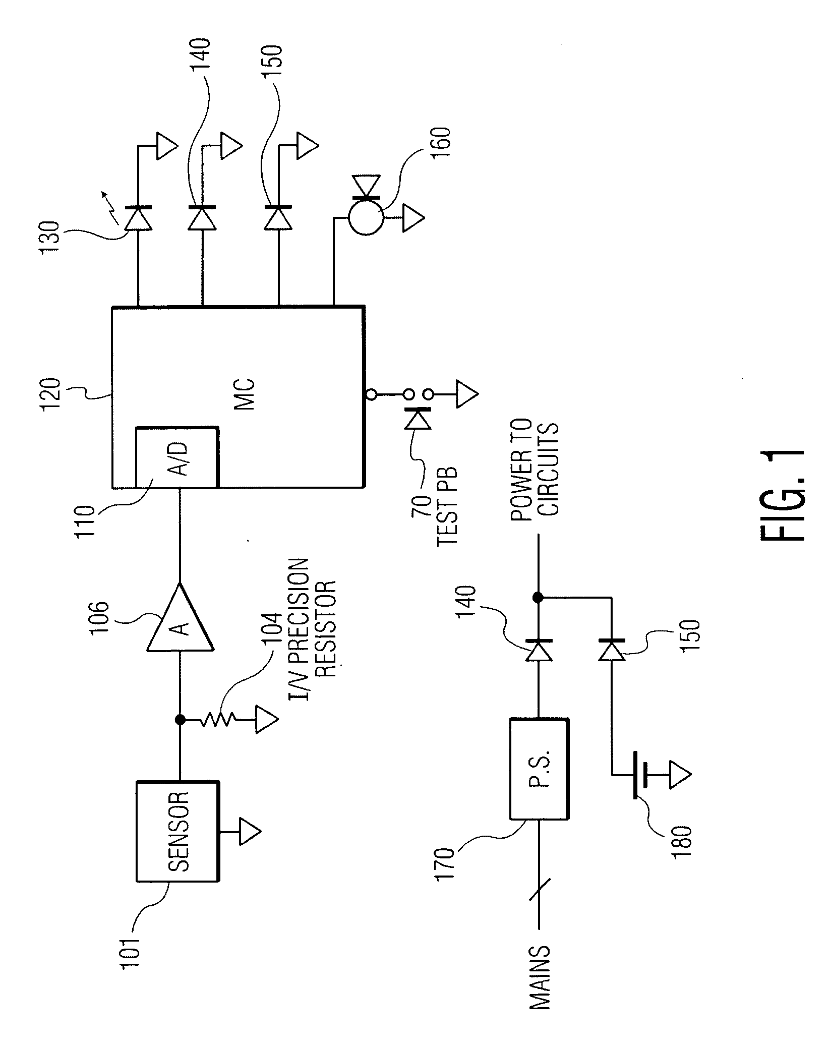

PUM


Abstract

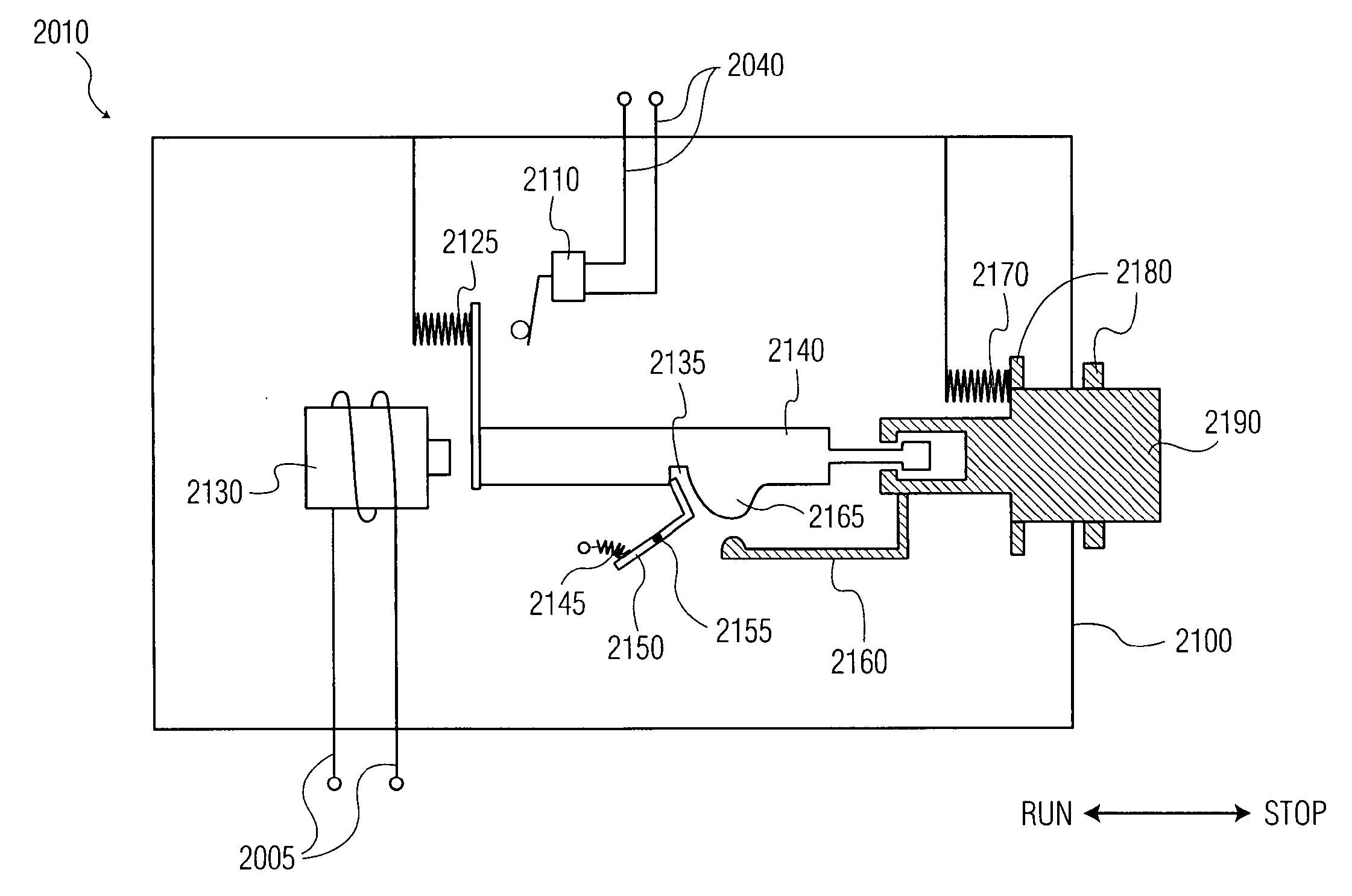
An electromechanical switch comprising a plunger, a first switch in contact with the plunger in a first position of the plunger, in which a connection of the switch is open, a button in sliding contact with the plunger, and a solenoid in contact with the plunger in a second position of the plunger, in which a connection of the first switch is closed.

Description

TECHNICAL FIELD OF THE INVENTION[0001]The present disclosures relate to a system and method of controlling the concentrations of one or more gases in a space. More specifically, the present disclosure relates to a system and method for preventing and controlling the concentration of gaseous products or byproducts, such as carbon monoxide (CO), in a space when a predetermined concentration is exceeded by interrupting the process, such as combustion, which produces the gases.BACKGROUND OF THE INVENTION[0002]The combustion or processing of certain materials often results in the production of certain gases. When the concentration of these gases exceeds a predetermined threshold, it may be desirable to cease the combustion or processing which is directly or indirectly producing the gas. One such gas is carbon monoxide. Carbon monoxide is a colorless, odorless, tasteless gas, which is produced through an incomplete combustion of a hydrocarbon. Carbon monoxide can be produced by various fu...

Claims


Application Information

Patent Timeline
Patent Type & Authority Applications(United States)
IPC IPC(8): H01H9/00
CPCB60K28/10F23N5/24H01H2300/018G01N33/0063G08B21/14G01N33/004G05B9/02G08B17/117
Inventor SID, ALBERTO
Owner MAF TECH
Why Eureka
Eureka Blog
Learn More