Method and apparatus for sample adaptive offset parameter estimationfor image and video coding

a technology of adaptive offset and image, applied in the field of method and apparatus for sample adaptive offset parameter estimation for image and video coding, can solve problems such as visual artifacts and quality/bit rate degradation

Active Publication Date: 2013-01-24
TEXAS INSTR INC
View PDF9 Cites 65 Cited by
  • Summary
  • Abstract
  • Description
  • Claims
  • Application Information

AI Technical Summary

Problems solved by technology

This leads to visual artifacts and quality / bit-rate degradation.

Method used


Image

  • Method and apparatus for sample adaptive offset parameter estimationfor image and video coding
  • Method and apparatus for sample adaptive offset parameter estimationfor image and video coding
  • Method and apparatus for sample adaptive offset parameter estimationfor image and video coding

Examples


first embodiment

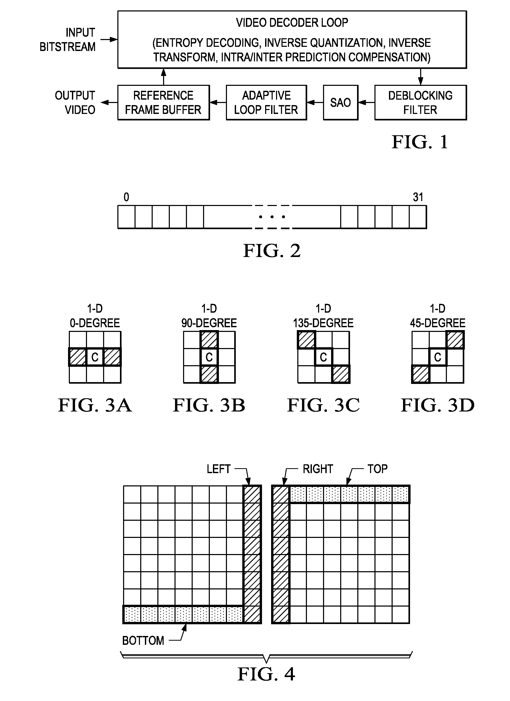
[0030 is to use all the non-deblock-filtered pixels in the LCU for the sample adaptive offset parameter estimation. In this case, the sample adaptive offset parameter estimation processing can be performed independently from the deblock filtering process. The estimated parameters will be applied to the sample adaptive offset processing for the deblock filtered pixels.

second embodiment

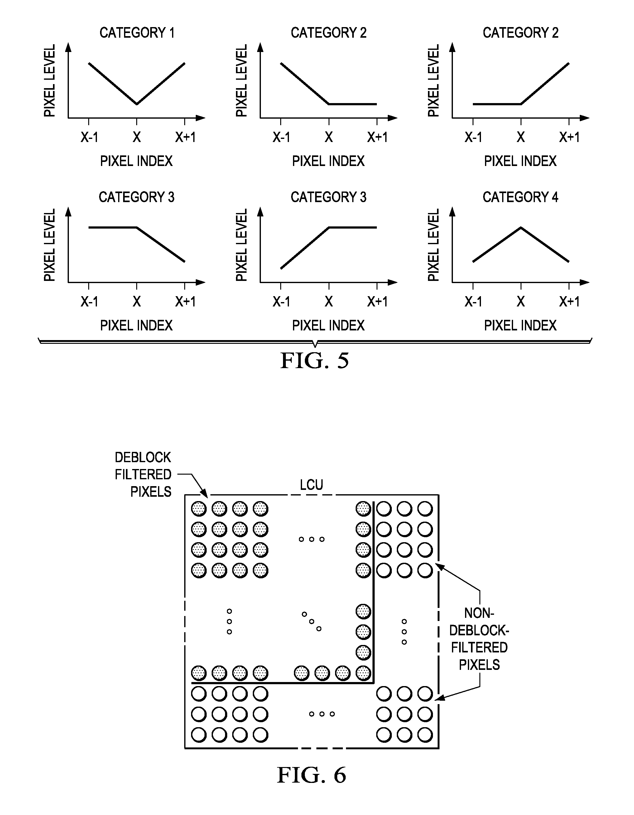
[0031 is to use both deblock filtered pixels and non-deblock-filtered pixels together as shown in FIG. 6. By use of this scheme, sample adaptive offset parameter estimation can be performed without waiting until the end of deblock filtering process of the LCU. Since this scheme uses deblock filtered pixels available in the LCU, this will improve the accuracy of sample adaptive offset parameter estimation.

third embodiment

[0032 is to wait until the end of coding of the right LCU, and use the deblock filtered pixels using the coded pixels in the right LCU. In this case, the bottom pixel lines are still not deblock-filtered. For low-latency processing, the non-deblock-filtered pixels are used for the sample adaptive offset parameter estimation. FIG. 6 shows the illustration of this case. This scheme will cause delay until the coding of right LCU, but will provide better accuracy of sample adaptive offset parameter estimation than the second embodiment.

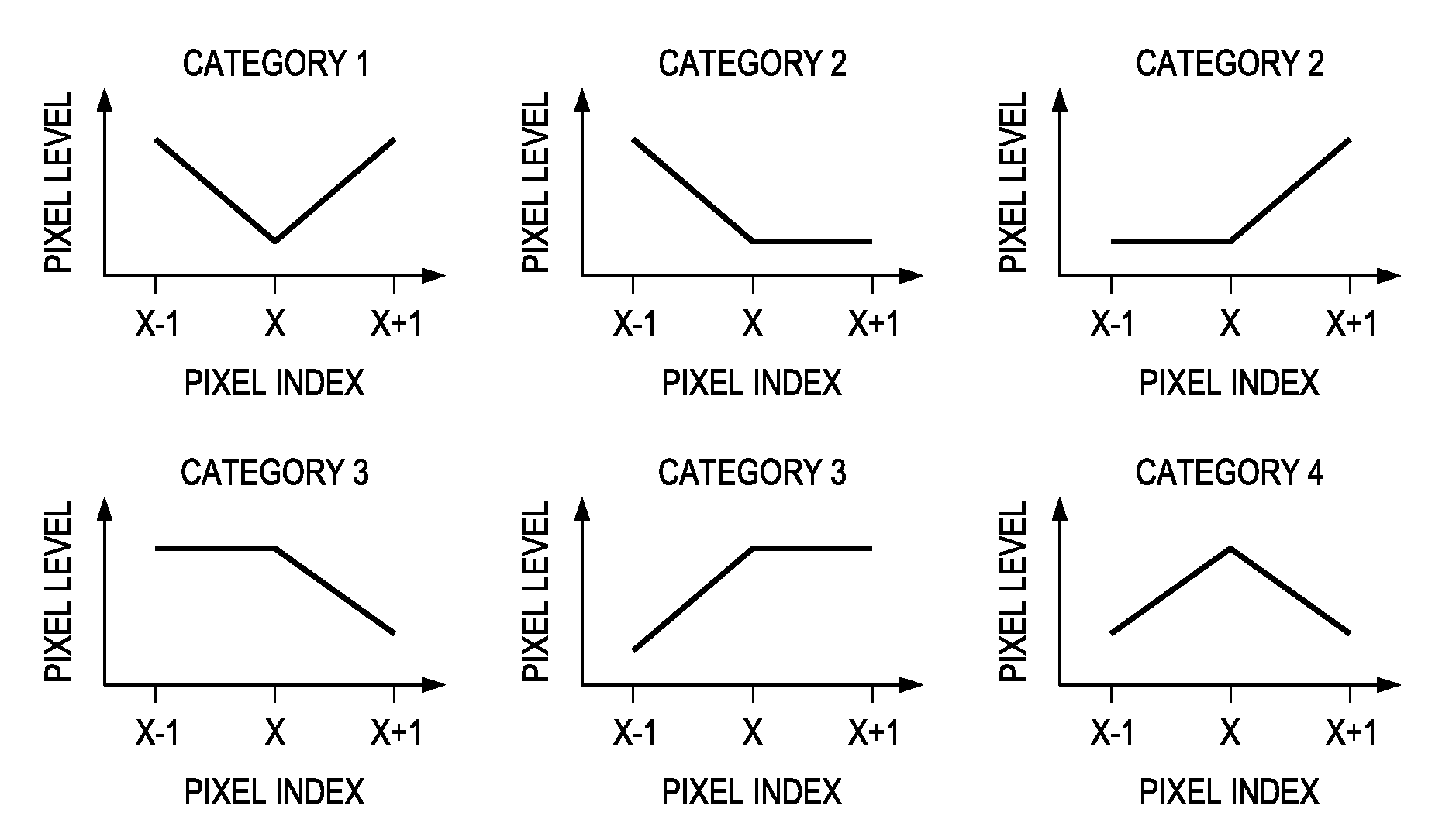
[0033]The area of deblock filtered pixels which can be used for sample adaptive offset parameter estimation can be adaptive to sample adaptive offset type. For example, when sample adaptive offset type 2, 3, or 4 is used, it requires looking at the pixels in the one line below of the current pixel to check edge shape. Therefore, 4 bottom lines are removed for sample adaptive offset parameter estimation, and can be replaced with non-deblock-filtered pixels...


PUM


Abstract

A method and apparatus for decoding video. The method includes determining a sample adaptive offset edge type of at least a portion of the image, determining a boundary edge type of the at least a portion of the image, modifying the sample adaptive offset edge type of the at least a portion of the image according to the determined edge type of the at least a portion of the image, selecting a sample adaptive offset type according to at least one of the determined sample adaptive offset edge type or the modified sample adaptive offset edge type, and filtering at least a portion of the image utilizing the selected filter type.

Description

CROSS-REFERENCE TO RELATED APPLICATIONS[0001]This application claims priority to U.S. Provisional Application No. 61 / 499,863, filed on Jun. 22, 2011, U.S. Provisional Application No. 61 / 500,280, filed on Jun. 23, 2011, U.S. Provisional Application No. 61 / 502,399, filed Jun. 29, 2011. This application claims priority to U.S. Provisional Application No. 61 / 607,069, filed Mar. 6, 2012, U.S. Provisional Application No. 61 / 608,386, filed Mar. 8, 2012 and U.S. Provisional Application No. 61 / 538,289, filed on Sep. 23, 2011 and U.S. Provisional Application No. 61 / 559,922, filed on Nov. 15, 2011. All of which are herein incorporated by reference.FIELD OF THE INVENTION[0002]This invention generally relates to a method and an apparatus for sample adaptive offset parameter estimation for image and video coding.BACKGROUND OF THE INVENTION[0003]Sample adaptive offset (SAO) was introduced for the next generation video coding standard called high efficiency video coding (HEVC). Sample adaptive offs...

Claims


Application Information

Patent Timeline
Patent Type & Authority Applications(United States)
IPC IPC(8): H04N7/26
CPCH04N19/176H04N19/61H04N19/167H04N19/14H04N19/82H04N19/117H04N19/174H04N19/86
Inventor BUDAGAVI, MADHUKAR
Owner TEXAS INSTR INC
Why Eureka
Try Eureka