Terminal for energization

Active Publication Date: 2013-01-31
TOYOTA JIDOSHA KK +1
View PDF4 Cites 1 Cited by
  • Summary
  • Abstract
  • Description
  • Claims
  • Application Information

AI Technical Summary

Benefits of technology

[0008]When a terminal member is provided with an engagement portion, the engagement portion may be subjected to a large stres

Problems solved by technology

When a terminal member is provided with an engagement portion, the

Method used


Image

  • Terminal for energization
  • Terminal for energization
  • Terminal for energization

Examples


Example

First Embodiment

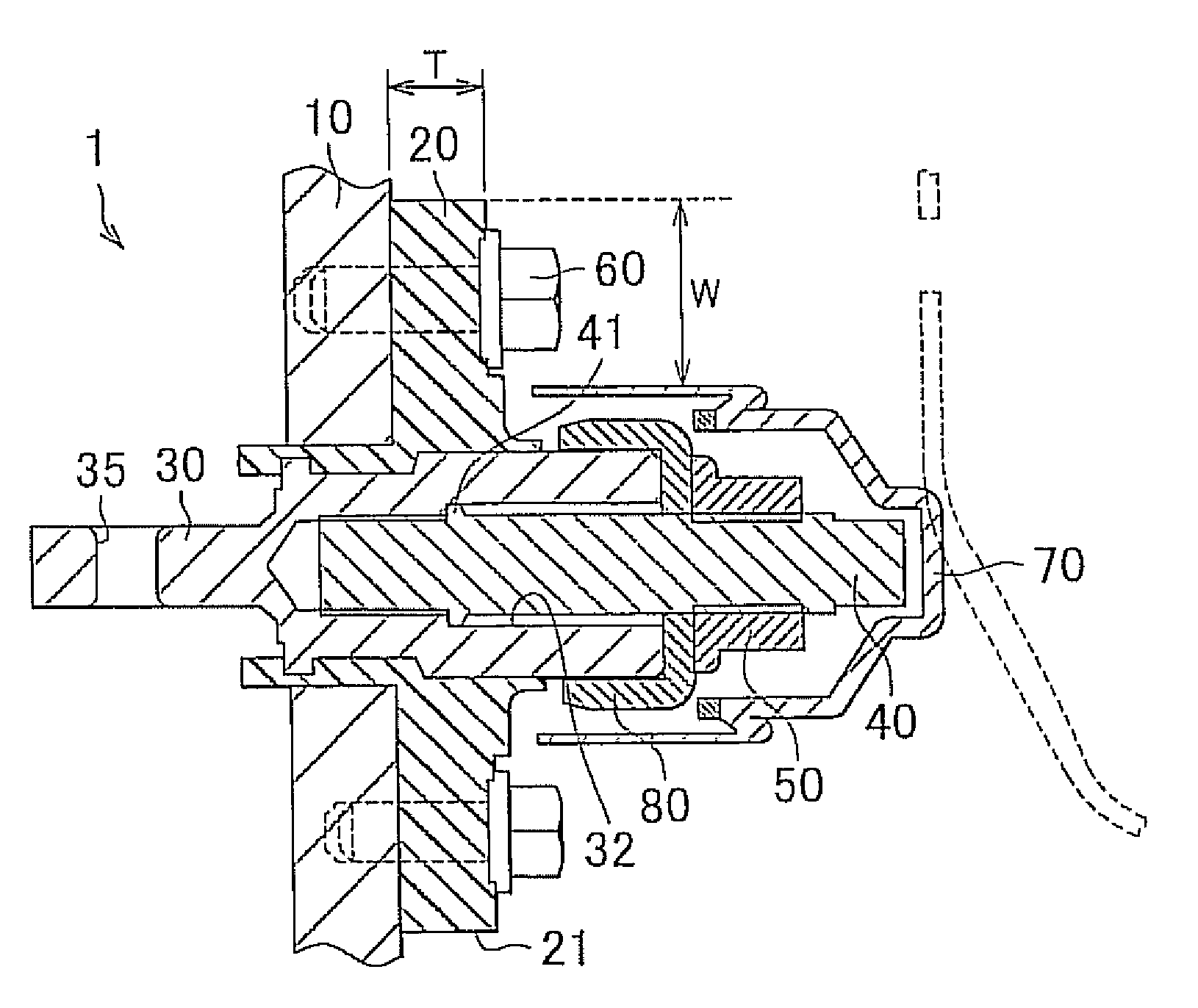
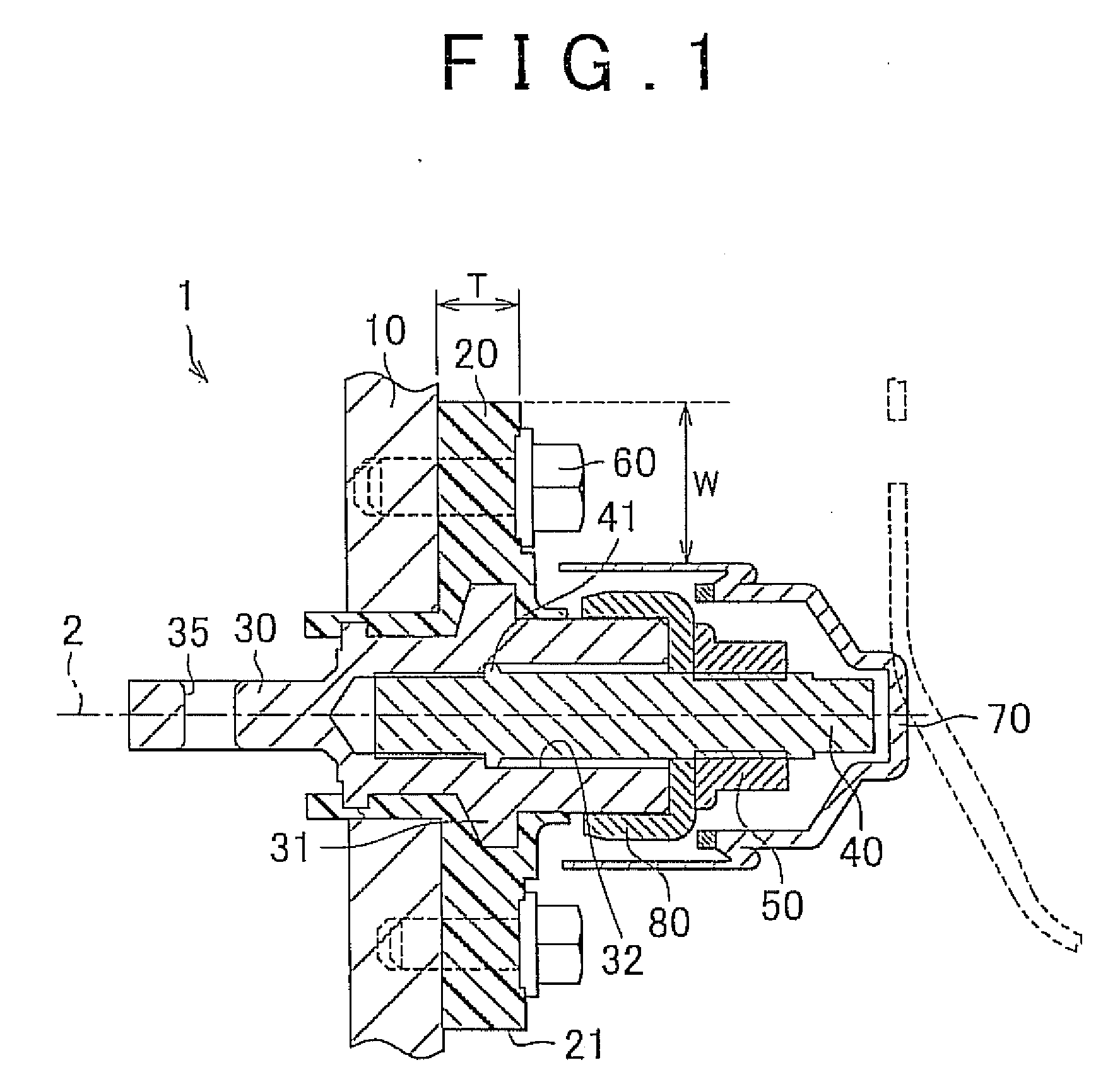
[0018]FIG. 1 is a cross-sectional view of a terminal for conduction that penetrates through a housing according to a first embodiment of the present invention. As shown in FIG. 1, a terminal for conduction 1 according to the first embodiment of the present invention includes an insulating member for fixation 20, a first terminal member 30, and a second terminal member 40. The insulating member for fixation 20 is fixed to a housing 10, and includes a flange portion 21 that extends along the housing 10 and that has a thickness T. The first terminal member 30 is provided to penetrate through the insulating member for fixation 20, and includes a tubular portion 32 that extends in the axial direction (direction of penetration) which is indicated by an arrow 2. The second terminal member 40 includes an engagement portion 41, and is inserted into the tubular portion 32 of the first terminal member 30. The second terminal member 40 is fixed to the first terminal member 30 th...

Example

Second Embodiment

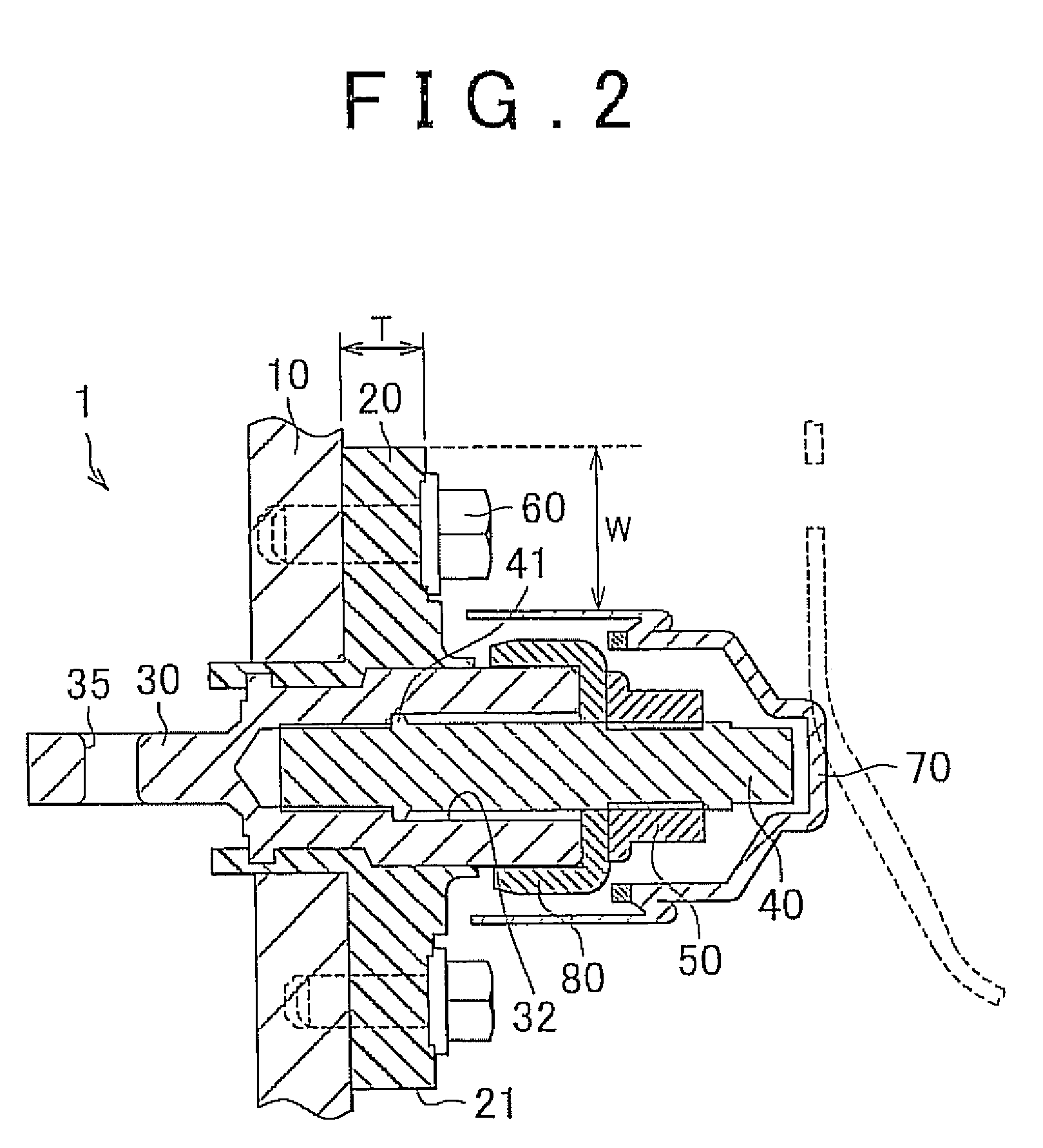
[0032]FIG. 2 is a cross-sectional view of a terminal for conduction that penetrates through a housing according to a second embodiment of the present invention. As shown in FIG. 2, the configuration according to the second embodiment is different from the configuration according to the first embodiment in that no projecting portion 31 is provided. The terminal for conduction according to the second embodiment can also achieve the same effect as that of the terminal for conduction 1 according to the first embodiment.

[0033]FIG. 3 shows a configuration according to the comparative examples in which no engagement portion is provided within the thickness of a flange portion. In the configuration according to the comparative examples, as shown in FIG. 3, the engagement portion 41 is disposed away from the insulating member for fixation 20. The round terminal 80, the nut 50, and the second terminal member 40 are covered by a cover 70.

[0034]In the configuration which is sho...


PUM


Abstract

A terminal for conduction includes an insulating member that is fixed to a housing and that includes a flange portion that extends along the housing; a first terminal member that is provided to penetrate through the insulating member and that includes a tubular portion, the first terminal member being conductive; and a second terminal member that includes an engagement portion and that is inserted into the tubular portion of the first terminal member, the second terminal member being fixed to the first terminal member through the engagement portion in the tubular portion and extending in an axial direction of the tubular portion. The engagement portion is positioned in a space between one surface and the other surface of the flange portion in the axial direction.

Description

INCORPORATION BY REFERENCE[0001]The disclosure of Japanese Patent Application No. 2011-162045 filed on Jul. 25, 2011 including the specification, drawings and abstract is incorporated herein by reference in its entirety.BACKGROUND OF THE INVENTION[0002]1. Field of the Invention[0003]The present invention relates to a terminal for energization, and more particularly to a terminal for energization in which two terminal members for energization are engaged with each other through an engagement portion.[0004]2. Description of Related Art[0005]Japanese Patent Application Publication No. 8-96866 (JP-8-96866-A) and Japanese Patent Application Publication No. 6-150989 (JP-6-150989-A), for example, disclose a terminal.[0006]JP-8-96866-A discloses a bush for a stud bolt terminal. The bush is provided at the outer periphery of the stud bolt terminal, and includes a groove portion that opens upward with the stud bolt terminal standing upright. The groove portion of the bush is provided with a g...

Claims


Application Information

Patent Timeline
IPC IPC(8): H01R4/24
CPCH01R13/04H01R13/748H01R13/10
Inventor YAMAMOTO, AKIRAHIRASHIMA, SHIGEO
Owner TOYOTA JIDOSHA KK
Why Eureka
Try Eureka