Stator and rotating electric machine

Active Publication Date: 2015-11-12
DENSO CORP
View PDF2 Cites 9 Cited by
  • Summary
  • Abstract
  • Description
  • Claims
  • Application Information

AI Technical Summary

Benefits of technology

[0011]With the above configuration, even if cracks are generated in the resin adhesive applied to the coil end parts of the stator coil due to a shock involved in operation of the rotating electric machine or a change in ambient temperature, the cracking stress will act in such a manner as to break up the adhesion between the resin adhesive and the outer coats of the electri

Problems solved by technology

However, during operation of the rotating electric machine, electric current flows in the electric wires forming the stator coil, causing the temperature of the electric wires to be increased due to the electrical resistances thereof.
In particular, when the rotating electric machine is used in a motor vehicle where a number of heat-generating machi

Method used


Image

  • Stator and rotating electric machine
  • Stator and rotating electric machine
  • Stator and rotating electric machine

Examples


first embodiment

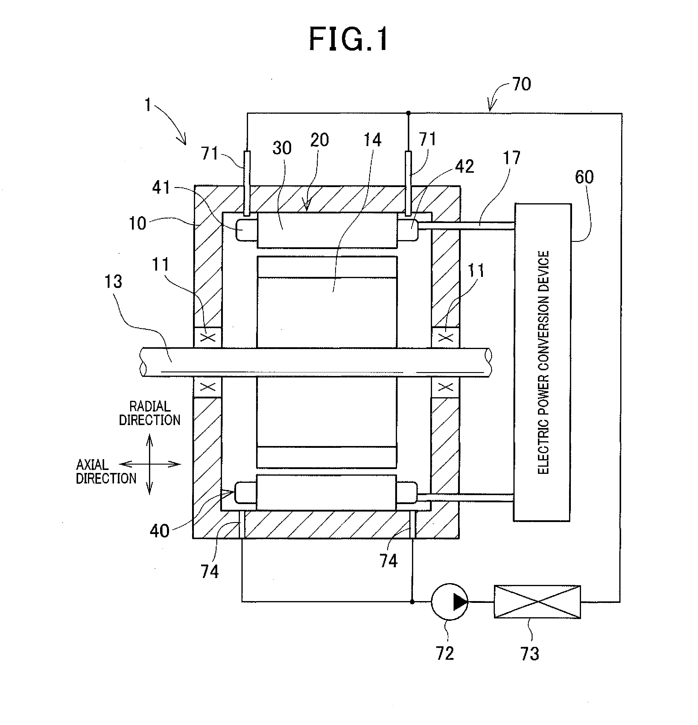
[0034]FIG. 1 shows the overall configuration of a rotating electric machine 1 according to the first embodiment.

[0035]In the present embodiment, the rotating electric machine 1 is configured as an inner rotor-type motor-generator for use in, for example, a motor vehicle. The motor-generator can selectively function either as an electric motor or as an electric generator.

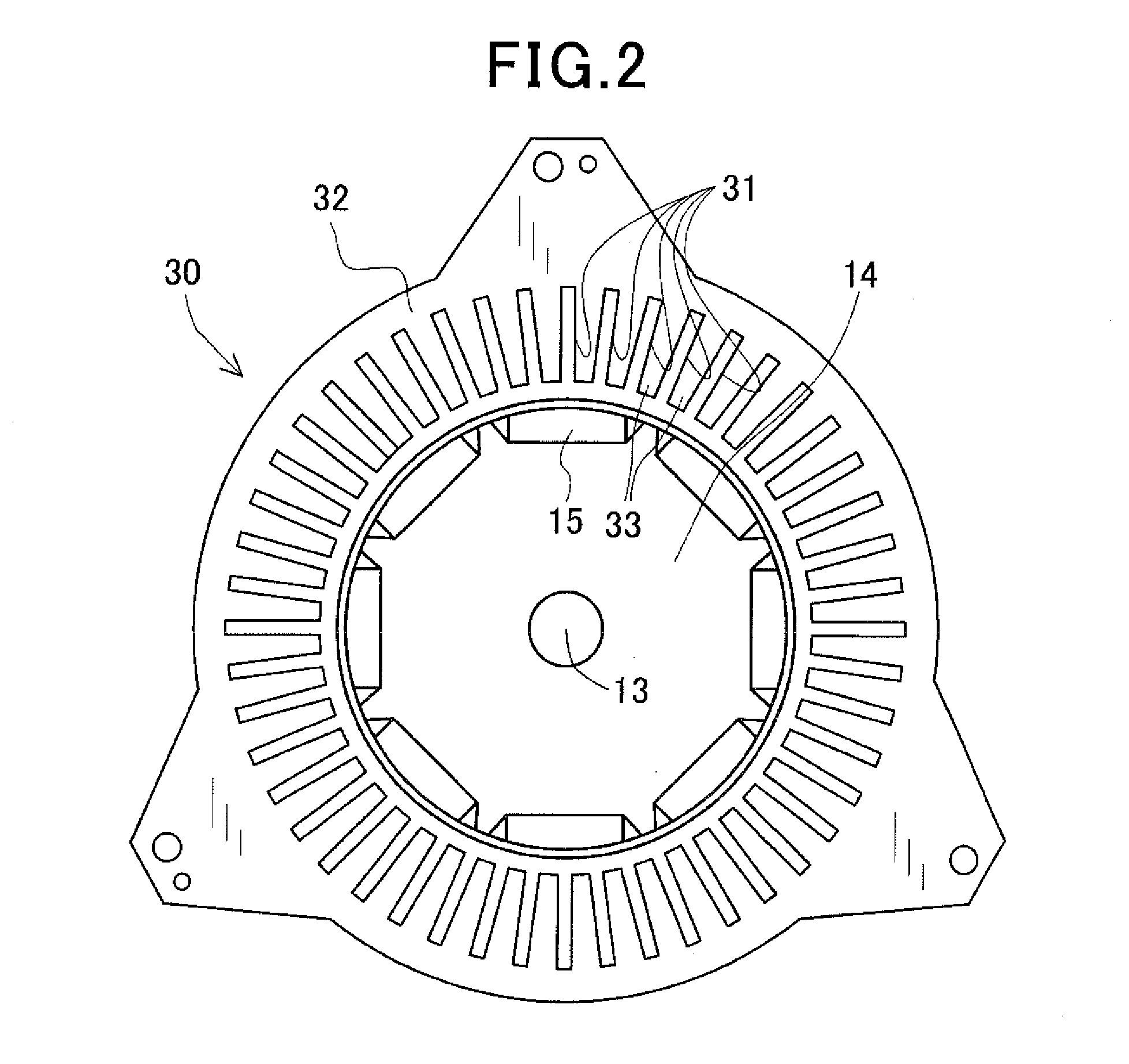
[0036]As shown in FIG. 1, the rotating electric machine 1 includes a housing 10, a rotating shaft 13, a rotor 14, a stator 20 that includes an annular stator core 30 and a three-phase stator coil 40, and a coolant supplier 70. Moreover, the rotating electric machine 1 is electrically connected with an electric power conversion device 60 via input / output lines 17. The housing 10 of the rotating electric machine 1 and a case member (not shown in the figures) of the electric power conversion device 60 may be either integrally formed into one piece or separately formed and then fixed together by fixing means. The fixing ...

second embodiment

[0081]A stator 120 according to the second embodiment will be described with reference to FIGS. 11-16.

[0082]The stator 120 according to the present embodiment is also designed to be used in the rotating electric machine 1 (see FIG. 1) described in the first embodiment.

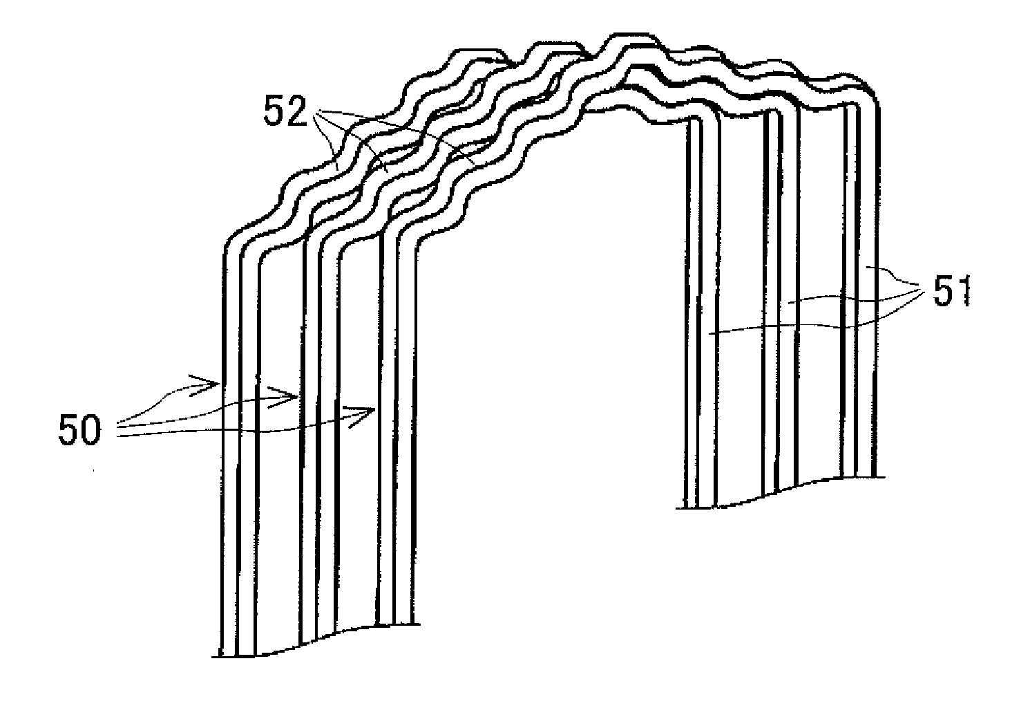
[0083]As shown in FIG. 11, the stator 120 includes an annular stator core 130, which is obtained by assembling a plurality of stator core segments 132 divided in its circumferential direction, and a stator coil 140 that is comprised of a plurality of continuous electric wires 150 mounted on the stator core 130.

[0084]Specifically, as shown in FIG. 12, the stator core 130 is comprised of the plurality (e.g., 24 in the present embodiment) of stator core segments 132 that are arranged in the circumferential direction of the stator core 130 so as to adjoin one another in the circumferential direction. On the radially outer surface of the stator core 130 (or the radially outer surfaces of the stator core segments 132), there...


PUM


Abstract

A stator includes an annular stator core, a stator coil and a resin adhesive. The stator coil is comprised of a plurality of electric wires. The electric wires are partially received in slots of the stator core so that the stator coil has a pair of coil end parts protruding outside the slots respectively from opposite axial end faces of the stator core. The resin adhesive is filled in the slots of the stator core and/or applied to the coil end parts of the stator coil. Moreover, each of the electric wires includes an electric conductor and an insulating coat that covers an outer surface of the electric conductor. The insulating coat is two-layer structured to include an inner coat and an outer coat. The adhesion strength of the outer coat to the resin adhesive is lower than the adhesion strength of the inner coat to the resin adhesive.

Description

CROSS-REFERENCE TO RELATED APPLICATION[0001]This application is based on and claims priority from Japanese Patent Application No. 2014-96807, filed on May 8, 2014, the content of which is hereby incorporated by reference in its entirety into this application.BACKGROUND[0002]1 Technical Field The present invention relates to stators and rotating electric machines that include the stators and are used in, for example, motor vehicles as electric motors and electric generators.[0003]2 Description of Related Art[0004]There are known rotating electric machines that are used in, for example, motor vehicles as electric motors and electric generators. Those rotating electric machines generally include a rotor and a stator. The stator includes an annular (or hollow cylindrical) stator core and a stator coil. The stator core is disposed in radial opposition to the rotor and has a plurality of slots that are formed in the stator core so as to be spaced from one another in the circumferential di...

Claims


Application Information

Patent Timeline
IPC IPC(8): H02K3/34H02K9/19H02K3/12H02K3/30H02K3/38
CPCH02K3/34H02K3/30H02K9/19H02K3/12H02K3/38H02K3/345H02K3/50H02K2213/03
Inventor TAKAHASHI, YUKISEGUCHI, MASAHIRO
Owner DENSO CORP
Why Eureka
Try Eureka