Steering test stand

US20130030720A1Active Publication Date: 2013-01-31DSPACE DIGITAL SIGNAL PROCESSING & CONTROL ENG

Image

  • Steering test stand
  • Steering test stand
  • Steering test stand

Examples


Embodiment Construction

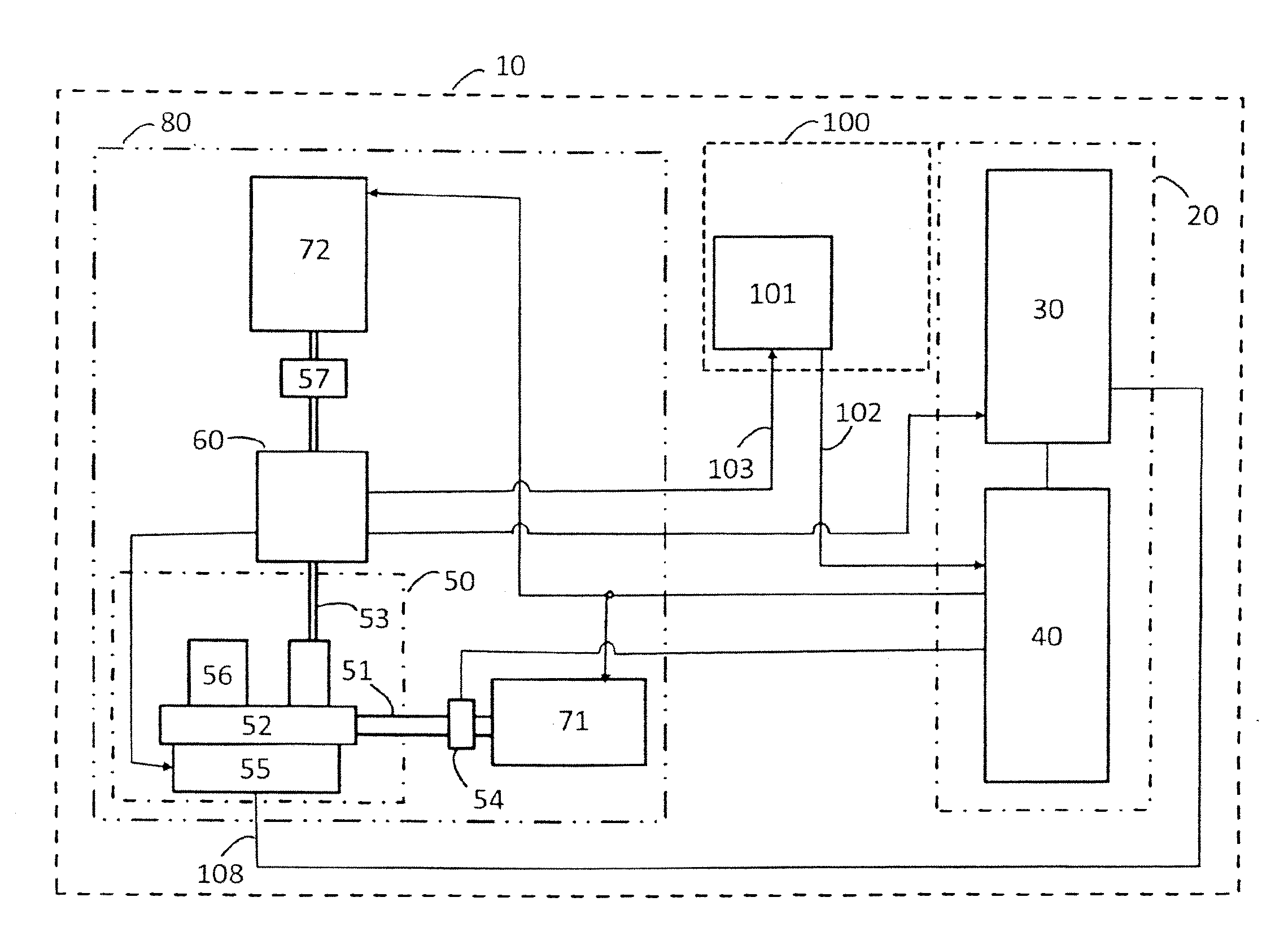
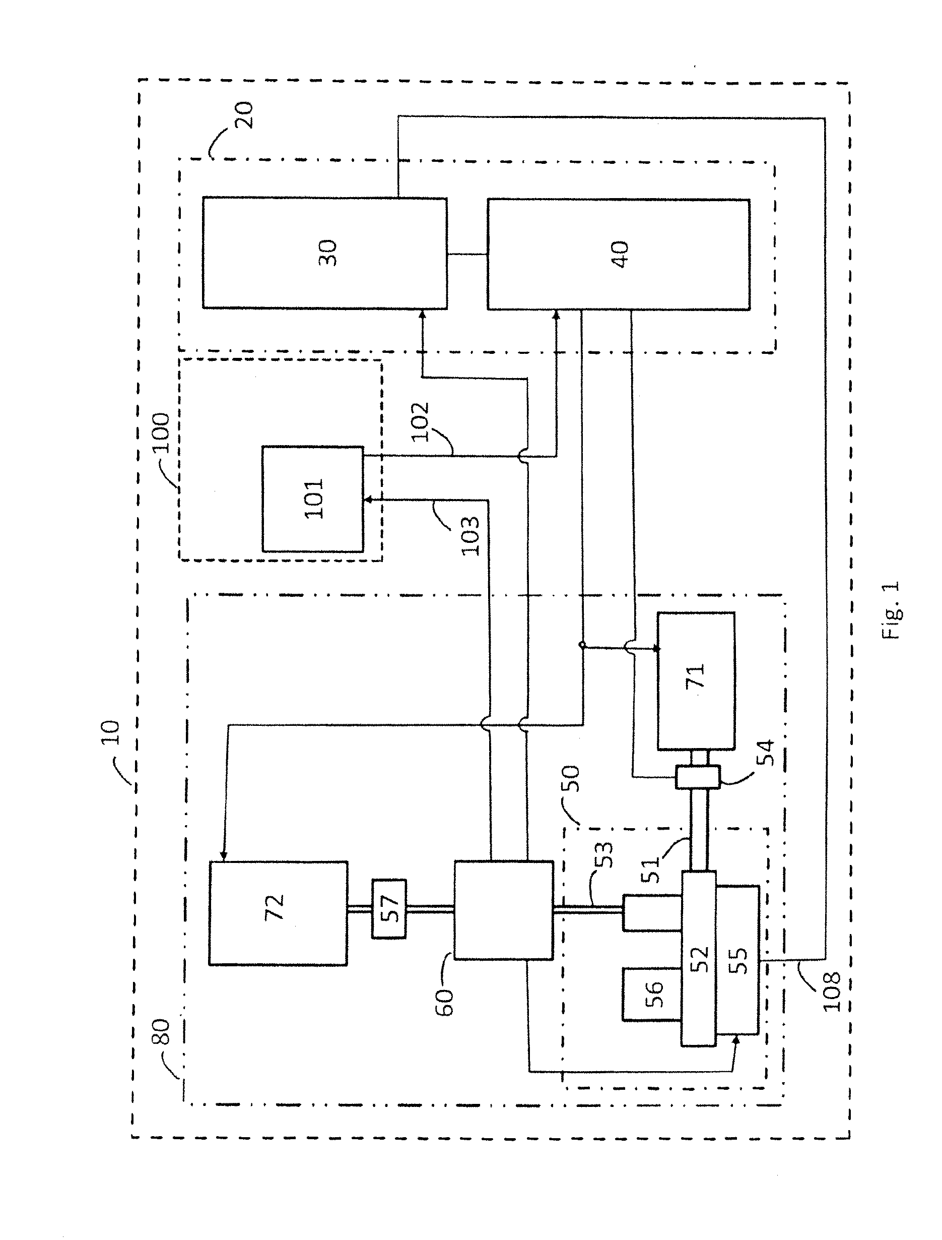
[0031]Referring to FIG. 1, steering test stand 1 is shown with a mechanical test stand 80, a driving simulator 20 and an inventive test driver unit 100.

[0032]The mechanical test stand 80 comprises a first steering device 50 with a steering gear 52, a steering rack 51, a steering column 53, a tie rod, a steering control unit 55 to be tested and a steering assistance unit 56 in the form of a servo motor or an EPS motor which is controlled by the steering control unit 55. A measurement device 60 for measuring a first value of a steering torque and an actual steering angle and / or an actual angular velocity is provided on the steering column 53 of the first steering device 50. The first value detected is transmitted to the test driver unit 100 via a connection. In addition, the test stand 80 has, for example, a first drive 71 as a steering rack drive in the form of a linear motor, a rotor motor or a spindle lift motor. The first drive 71 serves to apply forces to the first steering devic...


PUM


Abstract

A steering test stand has a first steering device with a measurement unit measuring the steering device torque value and applies forces to the steering device and control unit and has a control unit connected to a computer for controlling actuators. The computer simulates static and / or dynamic properties of a motor vehicle and transmits simulated target values to the control unit. A test driver unit comprises a second steering device as a force feedback steering wheel and a connection between the test driver unit and the computer, transmits a second steering angle set on the force feedback steering wheel. A second connection between the test driver unit and computer transmits steering torque measured on the first steering device to the test unit, such that the second steering device sets a second steering torque value on the force feedback steering wheel as a function of the first value.

Description

CROSS REFERENCE TO RELATED APPLICATION[0001]The present invention claims priority to German Patent Application No. 20 2011 050 806.4 filed on Jul. 26, 2011, which is herein incorporated by reference.FIELD OF THE INVENTION[0002]The field of the invention relates generally to automotive systems. In particular, the present invention is directed to steering test stands.BACKGROUND OF THE INVENTION[0003]Steering test stands such as those described, for example, at the website http: / / carts.micronova.de / hardware-in-the-loop / lenkungspruefstand.html comprise a steering device consisting of a steering system or a portion of a steering system with a steering gear, a steering assistance and a steering control unit for controlling the steering assistance.[0004]In addition, steering test stands comprise drives, e.g., gear rod drives and / or steering machines for applying forces or torques to the steering gear and / or adjusting a steering angle on the steering device. The drives comprise actuators an...

Claims


Application Information

Patent Timeline
31 Jan 2013
Publication
US20130030720A1
IPC
G06F19/00
CPC
G01M17/06
Inventors
SCHULTE, THOMAS; LEHMANN, ANDRE