
Oscillation device

Active Publication Date: 2013-02-14
NIHON DEMPA KOGYO CO LTD
View PDF3 Cites 4 Cited by
  • Summary
  • Abstract
  • Description
  • Claims
  • Application Information

AI Technical Summary

Benefits of technology

[0016]In the present invention, the oscillation device compensates the output frequency based on the detection result of an ambient temperature, and there is provided the compensation value obtaining unit obtaining, when oscillation frequencies of the first and second oscillation circuits are respectively set to f1 and f2, and oscillation frequencies of the first and second oscillation circuits at the reference temperature are respectively set to f1r and f2r, the frequency compensation value of f1 resulting from the ambient temperature being different from the reference temperature

Problems solved by technology

Normally, when a quartz-crystal oscillator is incorporated in an application to which quite high frequency stability is required, an oven controlled Crystal Oscillator (OCXO) is generally used, but the OCXO is formed of a large-scale device, and thus has a large power consumption.
For this reason, it is considered to use a Temperature compensated crystal oscillators (TCXO) with a simple structure and small power consumption, but the TCXO has a disadvantage that a frequency stability with respect to a temperature is inferior to that of the OCXO.
However, when the temperature compensation control is tried to be finely conducted, an amount of data for specifying the function of the frequency-temperature characteristic becomes large, and a large-capacity memory is required as the memory 95, resulting in that the memory 95 becomes expensive.
Further, a thermistor is normally used as the temperature detector, so that even when the amount of data is enlarged, an improvement in frequency accuracy cannot be expected due to a limit in detection accuracy of the temperature detector.
Further, since t

Method used


Image

  • Oscillation device
  • Oscillation device
  • Oscillation device

Examples


Example

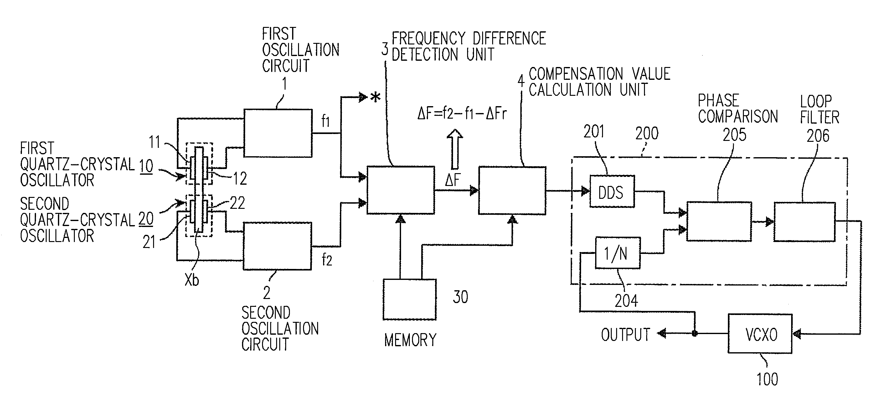
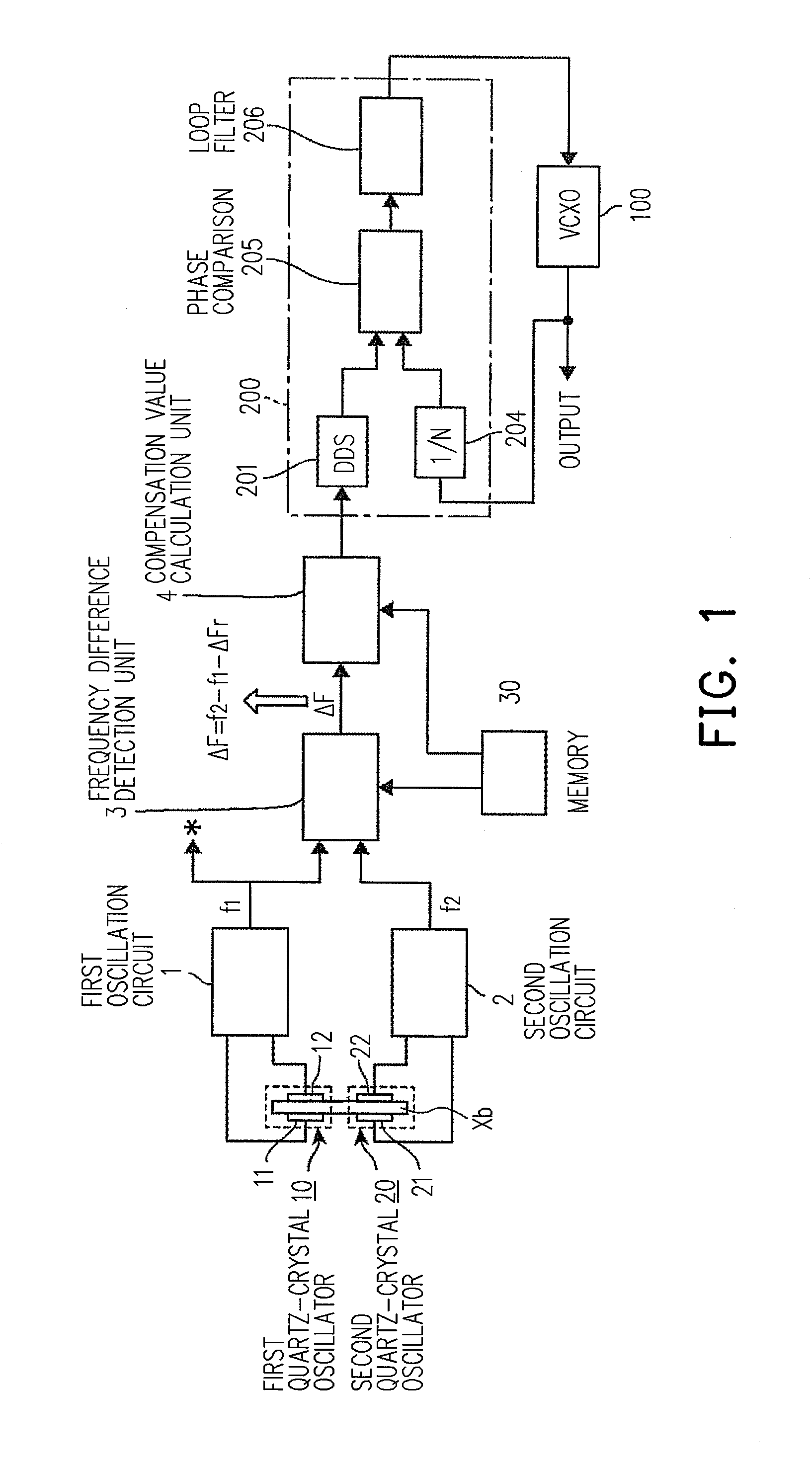
[0036]FIG. 1 is a block diagram showing an entire embodiment of an oscillation device of the present invention. This oscillation device is structured as a frequency synthesizer that outputs a frequency signal of a set frequency. The oscillation device includes a voltage controlled oscillator 100 using a quartz-crystal oscillator; a control circuit unit 200 that structures a PLL (Phase locked loop) in the voltage controlled oscillator 100; and a temperature compensation unit that performs temperature compensation of reference clock input into the control circuit unit 200. Although a reference numeral is not given to the temperature compensation unit, the temperature compensation unit corresponds to a part on the left side of the control circuit unit 200 in FIG. 1.

[0037]This control circuit unit 200 compares “a phase of reference (for reference) clock output from a Direct Digital Synthesizer (DDS) circuit section 201” with “a phase of clock as a result of frequency-dividing an output ...


PUM


Abstract

An oscillation device for reducing memory capacity includes a frequency difference detecting unit and a compensation value obtaining unit. When oscillation frequencies of the first and second oscillation circuits are respectively f1 and f2, and oscillation frequencies of the first and second oscillation circuits at a reference temperature are respectively f1r and f2r, the frequency difference detecting unit determines a difference corresponding value x corresponding to a difference value between a value corresponding to a difference between f1 and f1r, and a value corresponding to a difference between f2 and f2r. The compensation value obtaining unit obtains a frequency compensation value of f1 resulting from ambient temperature different from reference temperature based on the difference corresponding value x, and calculates the frequency compensation value of f1 by calculating nth-order polynomial for X being a value corresponding to x/k, where k is a divide coefficient specific to a device.

Description

CROSS-REFERENCE TO RELATED APPLICATION[0001]This application claims the priority benefit of Japan application serial no. 2011-173182, filed on Aug. 8, 2011. The entirety of the above-mentioned patent application is hereby incorporated by reference herein and made a part of specification.BACKGROUND OF THE INVENTION[0002]1. Field of the Invention[0003]The present invention relates to an oscillation device for detecting a temperature at which a quartz-crystal oscillator is placed, and for conducting temperature compensation of an output frequency based on a result of the temperature detection.[0004]2. Description of the Related Art[0005]Normally, when a quartz-crystal oscillator is incorporated in an application to which quite high frequency stability is required, an oven controlled Crystal Oscillator (OCXO) is generally used, but the OCXO is formed of a large-scale device, and thus has a large power consumption. For this reason, it is considered to use a Temperature compensated crysta...

Claims


Application Information

Patent Timeline
IPC IPC(8): H03K3/03
CPCH03L1/02
Inventor KOBAYASHI, KAORU
Owner NIHON DEMPA KOGYO CO LTD
Features
  • Generate Ideas
  • Intellectual Property
  • Life Sciences
  • Materials
  • Tech Scout
  • Unparalleled Data Quality
  • Higher Quality Content
  • 60% Fewer Hallucinations
Learn More