
Pitch period extracting apparatus of speech signal

Inactive Publication Date: 2005-11-22
SANYO ELECTRIC CO LTD
View PDF1 Cites 4 Cited by
  • Summary
  • Abstract
  • Description
  • Claims
  • Application Information

AI Technical Summary

Benefits of technology

[0016]Another object of the present invention in to provide a pitch period extracting apparatus in which it is possible to accurately extract a pitch period with a short processing time.
[0018]The delay time range determining means determines the delay times in calculating the autocorrelative values by the autocorrelative value calculating means on the basis of information of the sampling frequency. Therefore, it is possible to most suitably set the range of the delay times for extracting the pitch period. Therefore, according to the present invention, it is possible to calculate the pitch period with accuracy and it is possible to prevent a calculation amount from being increased.
[0023]In accordance with the present invention, even if a pitch period is short, the autocorrelative values are not weighted with extremely large weights, and therefore, the range of delay times in calculating the autocorrelative values may be narrow in comparison with the conventional first method. Therefore, a time for calculating the autocorrelative values becomes short, and a memory capacity necessary for calculating the autocorrelative values can be reduced.

Problems solved by technology

Therefore, there is not a possibility that double a true pitch period is erroneously evaluated as a pitch period in the first method; however, in the second method, there is a possibility that double a true pitch period is erroneously evaluated as a pitch period.
However, in comparison with the second method, the first method is disadvantageous in a point of a processing time.
Therefore, in the first method, there is a disadvantage that the processing time becomes long.
In other words, in the first method, there is an advantage that it is possible to extract a pitch period with precision but a disadvantage that the processing time is long, and in the second method, there is an advantage that the processing time is short but a disadvantage that there is a possibility that an erroneous pitch period is extracted.

Method used


Image

  • Pitch period extracting apparatus of speech signal
  • Pitch period extracting apparatus of speech signal
  • Pitch period extracting apparatus of speech signal

Examples


first embodiment

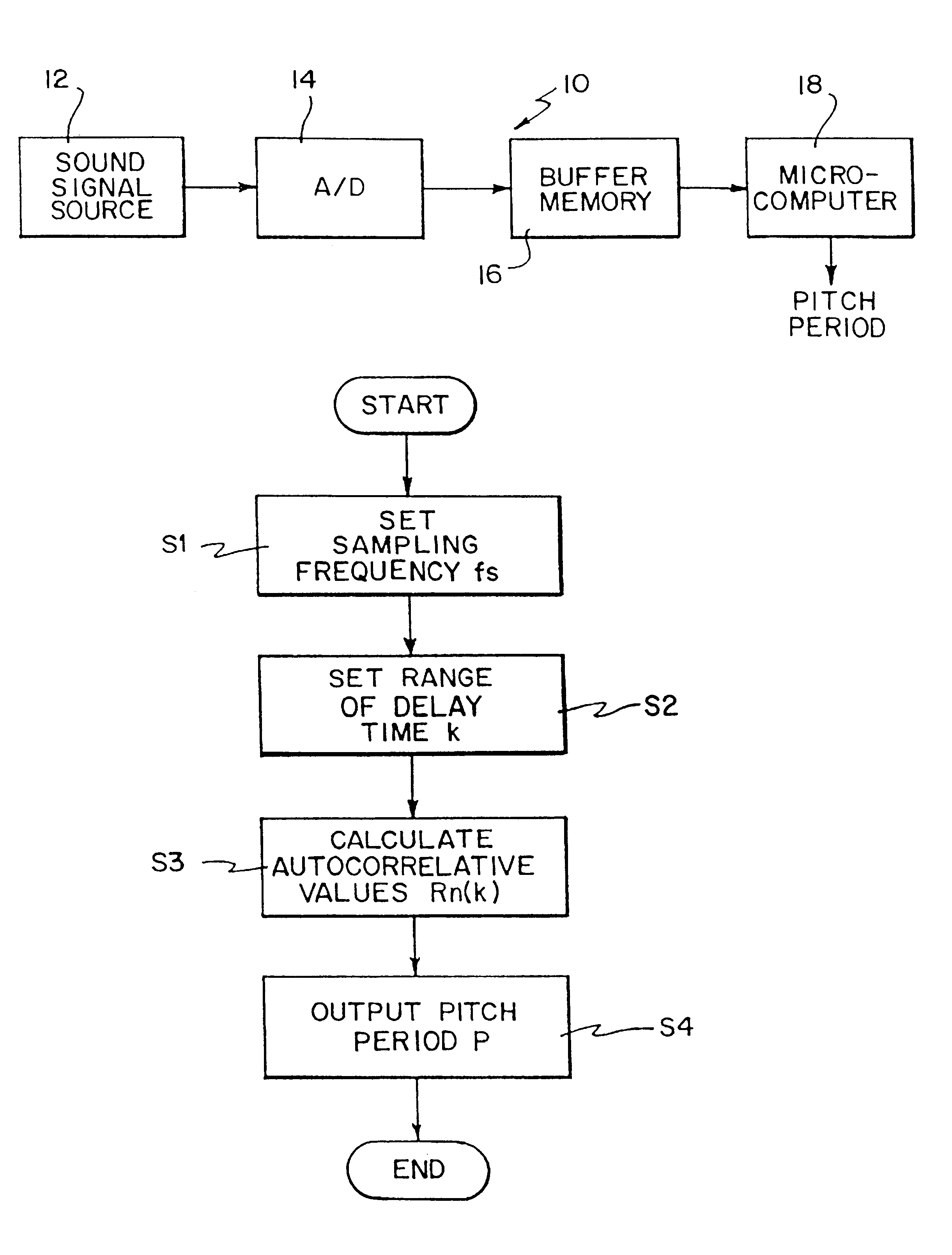
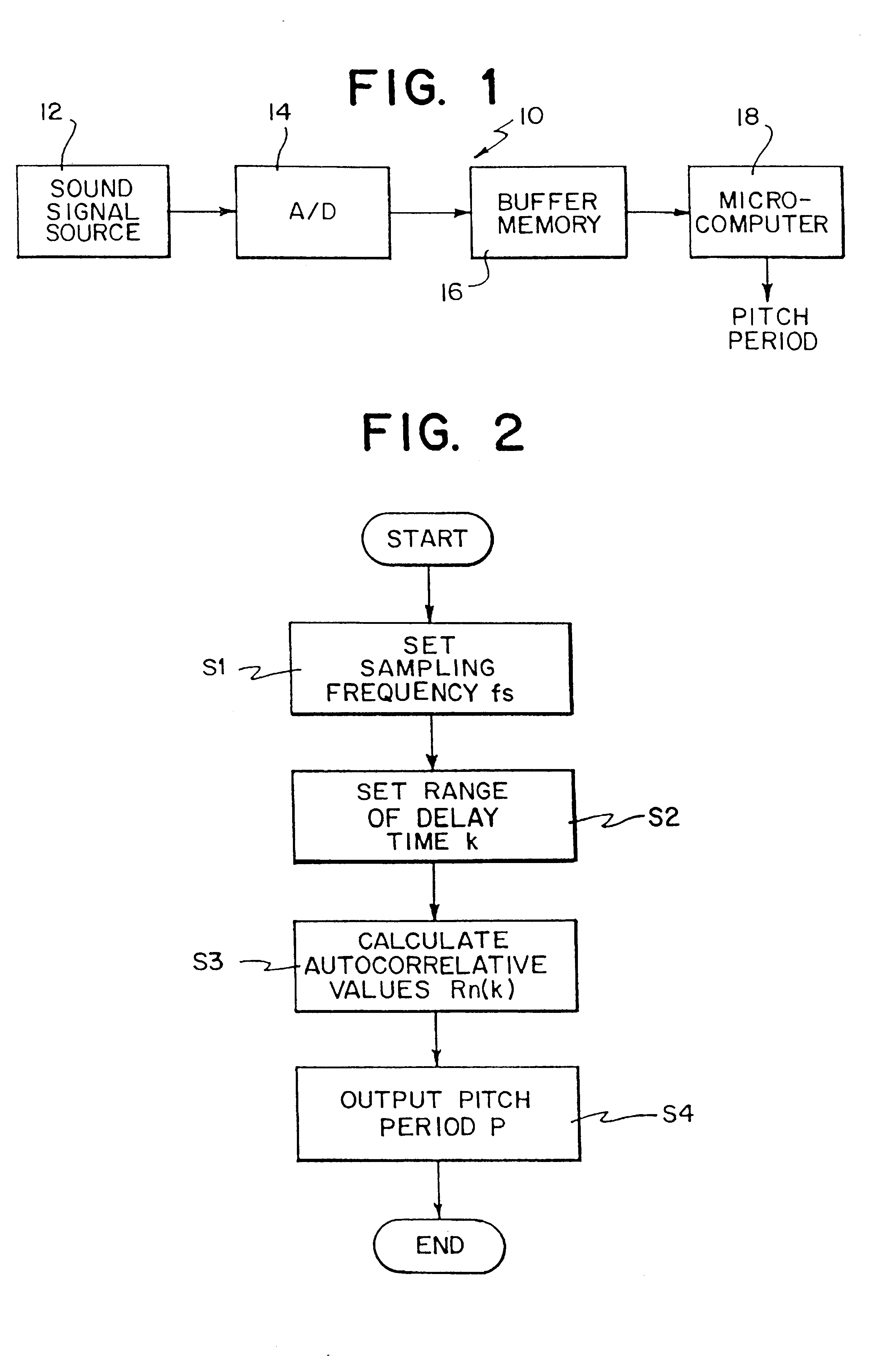
[0033]With referring to FIG. 2, in a first embodiment, the microcomputer 16 set the sampling frequency fs of the A / D converter 14, 8 kHz or 6 kHz, in a first step S1. According to the sampling frequency fs thus determined, the AID converter 14 converts the analog speech signal x(t) into speech signal data x(n). In a next step S2, the microcomputer 18 determines delay times k with referring to data of the sampling frequency fs in the first step S1. That is, in a case of the sampling frequency is 8 kHz, the microcomputer 18 sets the delay times k in the range of 20 samples≦k≦100 samples. In a case where the sampling frequency is 6 kHz, the microcomputer 18 sets the delay times k in the range of 15 samples≦k≦75 samples.

[0034]Then, in a step S3, the microcomputer 18 sequentially reads-out the speech signal data x(n) stored in the buffer memory 16, and calculates the autocorrelative values Rn(k) on the basis of the following equation (3) and according to the delay times k set in the step...

second embodiment

[0036]In the second embodiment, the microcomputer 18 sets a most suitable range of the delay times k according to the sampling frequency fs. In contrast, in FIG. 3 embodiment, the microcomputer 18 sets a plurality of periods within the range of the delay times k in calculating the autocorrelative values Rn(k),

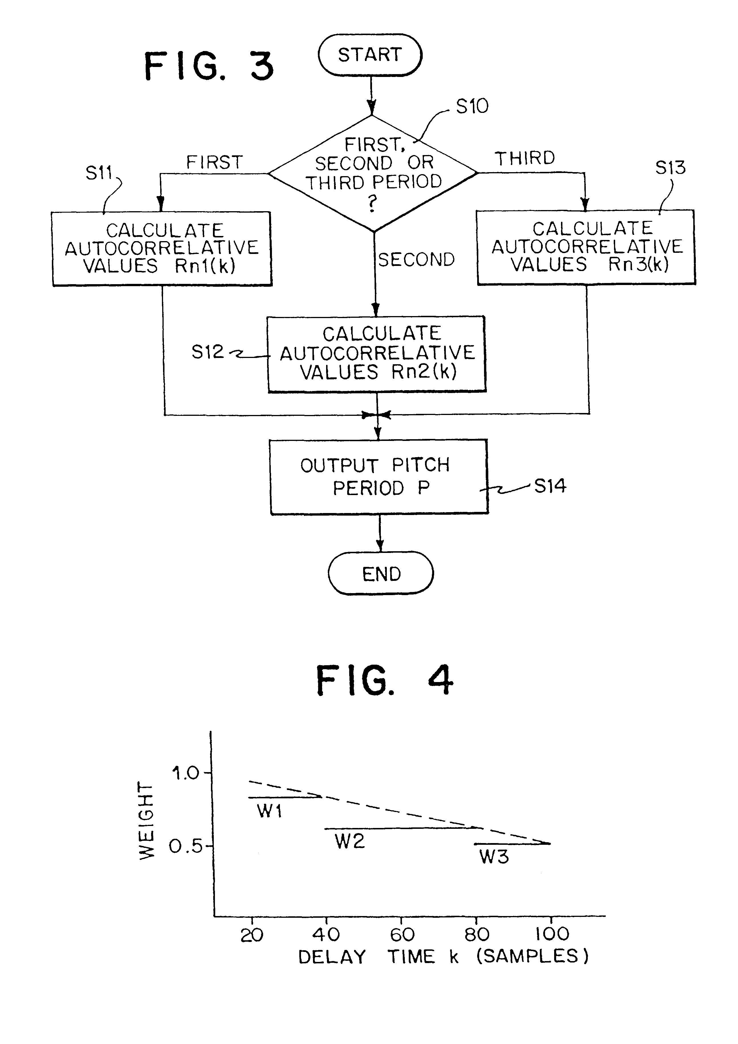
[0037]More specifically, in this embodiment shown, the microcomputer 18 divides the range of the delay times k which is a pitch period searching time period in calculating the autocorrelative values Rn(k) into a plurality of periods. In such a case, respective starting values and end values of the respective periods are determined such that the end value of the period does not include double the starting value of that period. Then, autocorrelative values Rn1(k), Rn2(k) and Rn3(k) of the respective periods are calculated.

[0038]With referring to FIG. 3, in a first step 510, the microcomputer 18 determines the plurality of periods within the range of the delay times k according to...

third embodiment

[0047]FIG. 5 is a flowchart showing a third embodiment in which the FIG. 2 embodiment (a first embodiment) and FIG. 3 embodiment (a second embodiment) are simultaneously included. In a step 520 of FIG. 5, the microcomputer 18 sets a sampling frequency fs of the A / D converter 14, that is, 8 kHz or 6 kHz. The A / D converter 14 converts the analog speech signal into the speech signal data x(n) with the sampling frequency fs thus set. In a next step 521, the microcomputer 18 determines the respective periods within the range of the delay times k with referring to the data of the sampling frequency fs in the step 51. That is, when the sampling frequency fs is 8 kHz, a range of 20 samples≦k<40 samples, a range of 40 samples≦k<80 samples, and a range of 80 samples≦k≦100 samples are set as the first period, the second period, and the third period. In addition, if the sampling frequency fs is 6 kHz, a range of 15 samples≦k <30 samples, a range of 30 samples≦k<60 samples, and a range of 60 sam...


PUM


Abstract

A pitch period extracting apparatus includes a microcomputer which determines a sampling frequency for an A / D converter, and a range of delay times for calculating autocorrelative values on the basis of the sampling frequency. For example, the delay times are set within a range of 20 samples≦k≦100 samples in a case of 8 kHz, and a range of 15 samples≦k≦75 samples in a case of 6 kHz. The microcomputer calculates the autocorrelative values of speech signal data stored in a buffer memory, and outputs a delay time at which a maximum autocorrelative value is obtainable as a pitch period of an inputted speech signal.

Description

BACKGROUND OF THE INVENTION[0001]1. Field of the Invention[0002]The present invention relates to a pitch period extracting apparatus of a speech signal. More specifically, the present invention relates to a pitch period extracting apparatus which extracts a pitch period of an inputted speech signal by evaluating a delay time at which a maximum autocorrelative value is obtainable.[0003]2. Description of the Prior Art[0004]As methods for extracting a pitch period of a speech signal with utilizing autocorrelative values, two methods are known. A first method is a method utilizing a short-time autocorrelation, and a second method is a method utilizing a modified short-time autocorrelation.[0005]In the first method, it is assumed that the speech signal in restricted in time, and autocorrelative values are evaluated by regarding as that the speech signal exists within only a period of a time length Ts and the speech signal is always zero out of the period. In the second method, it is assu...

Claims


Application Information

Patent Timeline
IPC IPC(8): G10L25/90
CPCG10L25/06G10L25/90G10L13/00
Inventor INOUE, TAKEO
Owner SANYO ELECTRIC CO LTD
Learn More