[0020] Hereinafter, referring to the drawings, the explanation will be given below concerning embodiments of the present invention. Through all of the drawings, same reference numerals will be used to designate similar members.
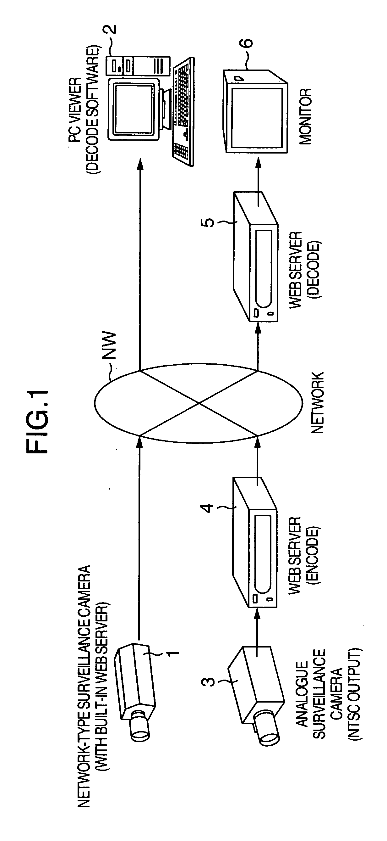
[0021]FIG. 1 is a schematic diagram for illustrating the configuration of a general surveillance system. A network-type surveillance camera 1 and an analogue surveillance camera 3 are set up at each surveillance point or site, thereby taking images of a surveillance target, the images being main data. After applying a compression processing to the images taken, the network-type surveillance camera 1 sends out the compressed images to a network NW. The images taken by the analogue surveillance camera 3 are supplied to a WEB server 4, then being subjected to the compression processing in this WEB server 4. After that, the compressed images are sent out to the network NW. Meanwhile, in the surveillance center, a PC viewer 2, a WEB server 5, and a monitor 6 are placed. These devices decode and display the compression-processed camera images transmitted via the network NW as described above. A decoding apparatus according to the present invention is mounted in the PC viewer 2 and the WEB server 5.
[0022]FIG. 2 is a block diagram for illustrating an embodiment of the decoding apparatus according to the present invention. This decoding apparatus includes a compressed-data input line (i.e., input unit) 1-0, a compressed-data switch unit 1-1, a decoding processing unit 1-2, a superposition processing unit 1-3, a sub-data memory unit 1-4, and a control unit 1-5. One set or plural sets of sub data (such as appliance (machine) information on the cameras and information on each surveillance point or site) to be superposed on the main data is stored in the sub-data memory unit 1-4 in a compression-encoded form. The compressed-data switch unit 1-1 selects and outputs, at a predetermined timing, either of the compressed main data received via the network NW which, hereinafter, will be simply referred to as “compressed main data” and the compressed sub data read out of the sub-data memory unit 1-4 which, hereinafter, will be simply referred to as “compressed sub data”. This selection operation in the compressed-data switch unit 1-1 is specified by the control unit 1-5. The sub data to be read out may also be specified by the control unit 1-5 in selecting the sub-data memory unit 1-4.
[0023] Also, the decoding processing unit 1-2 performs a decoding processing on the compressed main data and the compressed sub data that are selected and outputted from the compressed-data switch unit 1-1. The superposition processing unit 1-3 includes a working memory 1-30 such as a RAM. Then, using the working memory 1-30, the superposition processing unit 1-3 temporarily stores the decoded main data supplied from the decoding processing unit 1-2, superposes the subsequently supplied decoded sub data on the decoded main data on the working memory 1-30, and outputs the decoded main data and sub data in superposition to the monitor 6 or the like.
[0024] Next, the explanation will be given of the operation of the decoding apparatus configured in this way. FIG. 3 is a flow chart for illustrating the procedure and contents of the operation of this decoding apparatus.
[0025] Here, it is assumed that the compressed main data 1-(A) is received from the network NW. Also, it is assumed that, as illustrated in FIG. 2, data desired to be superposed on output data 1-(D) is data equivalent to one-half of the frame in the SDTV scheme. Its data size is equal to about 350 KB. A compression-encoding processing according to, e.g., the JPEG (Joint Photographic imaging coding Experts Group) is applied to this data to be superposed and the resultant compression-encoded data is stored in advance in the sub-data memory unit 1-4 as the compressed sub data 1-(E). In this case, if the setting for the compression-encoding processing is made to a high picture-quality, the data size of the compressed sub data 1-(E) becomes about 21 KB. Also, it is assumed that both of the compressed main data 1-(A) and the compressed sub data 1-(E) have been compressed by the same compression-encoding scheme.
[0026] First, explanation will be given of the basic operation which performs no superposition processing. Having received the compressed main data 1-(A) from the network NW, the compressed-data switch unit 1-1 inputs the compressed main data 1-(A) to the decoding processing unit 1-2. The decoding processing unit 1-2 performs decoding processing on the compressed main data 1-(A), then outputting the main data in the baseband as decompressed data 1-(C). The decompressed data 1-(C) is then inputted to the superposition processing unit 1-3 and temporarily stored in the working memory 1-30. After that, the decompressed data 1-(C) is outputted as the output data 1-(D) in response to an output request from the system.
[0027] Next, explanation will be given of the operation which performs the superposition processing. FIG. 3 is a flow chart for illustrating the procedure and contents of the operation of the decoding apparatus illustrated in FIG. 2. Also, FIG. 4 is a time chart for illustrating the decoding operation in this decoding apparatus.
[0028] In FIG. 3, in step S31, the compressed-data switch unit 1-1 is set to the input side of the compressed main data 1-(A). In step S32, the compressed main data 1-(A) received through the above-described procedure is decoded, then being inputted to the superposition processing unit 1-3 as the decompressed data 1-(C).
[0029] Here, in step S33, the processing goes to a step S34 at a predetermined compressed-data input timing. In step S34, the compressed-data switch unit 1-1 is switched to the input side of the compressed sub data 1-(E). Then, in step S35, desired compressed sub data 1-(E) is outputted from the sub-data memory unit 1-4, then being inputted into the decoding processing unit 1-2. The decoding processing unit 1-2 performs decoding processing on the compressed sub data 1-(E) and outputs the sub data in the baseband as decompressed data 1-(C) which in turn is outputted to the superposition processing unit 1-3. The superposition processing unit 1-3 outputs superposed data which results from superposing the sub data on the temporarily-stored main data.
[0030] Referring to FIG. 4, explanation will be given of the above-described superposition processing procedure in more detail.
[0031] When the input of the compressed main data is selected, the compressed main data is inputted to the decoding processing unit 1-2 and decoded therein. Then, the decoded main data is stored in the working memory 1-30 which is provided in the superposition processing unit 1-3. Subsequently, if the input request for the compressed sub data is made (i.e., the step S33 in FIG. 3), the compressed-data switch unit 1-1 is switched to the sub-data side to select the input of the compressed sub data. Accordingly, the desired compressed sub data is read out of the sub-data memory unit 1-4, then being inputted to the decoding processing unit 1-2 so as to be decoded. The decoded sub data is stored in the working memory 1-30 in the superposition processing unit 1-3. In the superposition processing unit 1-3 the stored main data and sub data are superposed on each other and outputted
[0032] As having been described so far, in the above-described embodiment, the sub data to be superposed is compression-encoded, then being stored in the sub-data memory unit 1-4 in advance. And, depending on the requirements (e.g., after the decoding processing for the 1-frame or more main data has been finished, or at a specified interrupt time or a specified timing), the compressed sub data is decoded so as to be superposed on the earlier-decoded main data. This configuration makes it possible to tremendously reduce the memory capacity, thereby allowing achievement of the small-size implementation and low-price implementation of the system.
[0033] Take for example a SDTV-scheme image superposition system, the image data equivalent to 1 frame in the SDTV scheme is equal to about 700 KB. Accordingly, if it is assumed that the image superposition of one-half of the 1 frame is to be carried out, the data to be superposed needs to be accumulated by about 350 KB. Moreover, if the image superposition is implemented by switching between 10 patterns of image superposition, the memory capacity of as much as about 3. 5 MB becomes necessary. In the above-described embodiment, if the setting for the sub-data compression-encoding processing is set to a high picture-quality, the data size of the compressed sub data 1-(E) becomes equal to about 21 KB. Consequently, in this example, about a 94% reduction in the memory capacity becomes accomplishable.
[0034] Note that this invention is not limited to the above-described embodiment. For example, although the image compressed data has been selected as the target compressed data, it is also possible to deal with various types of information such as voice data or character data. Also, the JPEG has been selected as the compression-encoding scheme for the target compressed data, it is also possible to deal with the other compression-encoding schemes.
[0035] In the present embodiment, it has been assumed that the compressed main data 1-(A) is the compressed data which is received from a transmission infrastructure such as the network NW. As the compressed main data 1-(A), however, whatever compressed data is allowable as long as it is the compressed data which can be inputted from the outside of the decoding apparatus. Therefore the compressed main data may include not only the input from the transmission infrastructure, but also an input from a storage appliance such as RAM and so on.
[0036] Further, although it has been assumed that the compressed sub data 1-(E) is stored in advance in the sub-data memory unit 1-4, the compressed sub data 1-(E) may also be updated using the data received from a transmission infrastructure such as the network during the operation of the surveillance system, or the compressed input data from a storage appliance such as RAM.
[0037] Further, in the present embodiment, it has been assumed that the compressed main data 1-(A) and the compressed sub data 1-(E) are the data compression-encoded by the same compression-encoding scheme. However, mutually different compression-encoding schemes may be used. FIG. 5 illustrates the configuration of a decoding apparatus in this case. A first decoding processing unit 1-21 performs decoding processing corresponding to the compression-encoding scheme for the compressed main data 1-(A). A second decoding processing unit 1-22 performs decoding processing corresponding to the compression-encoding scheme for the compressed sub data 1-(E). Furthermore, after the decoding processing of the respective compressed data have been finished, an input switching between the respective decoded data is performed by the compressed-data switch unit 1-1. Also, the configuration in FIG. 5 is of course also applicable to the case where the same compression-encoding scheme is used for the compressed main data 1-(A) and compressed sub data 1-(E). This allows the decoding of the respective compressed data to be performed in the decoding processing units 1-21 and 1-22, respectively. Consequently, it becomes possible to increase the entire processing speed.
[0038] Also, while only one kind of the sub data to be superposed is assumed in the embodiments above, thereby requiring the use of only one sub-data memory unit 1-4 involving only one kind of the compressed sub data 1-(E), it is also possible to provide an increased number of sub-data memory units and compressed sub data correspondingly, when the number of the kinds of the data to be superposed is increased in response to a system request. In this case, the compressed-data switch unit 1-1 may be equipped with a switching function corresponding to the number of the plural kinds of compressed sub data. Alternatively, the only one sub-data memory unit may be configured to store plural kinds of compressed sub data in such a manner that arbitrary compressed sub data is readable so that desired sub data may be read by the control unit 1-5 (FIG. 2).
[0039] Here, the configuration of the decoding apparatus according to the present invention is not necessarily limited to the above-described ones. Instead, various configurations are also employable. Further, the present invention can also be provided as, e.g., methods or schemes for executing the processing according to the present invention, or programs for implementing these methods or schemes, or record media for recording the programs. Also, the present invention can also be provided as various apparatuses or systems.
[0040] Also, the application field of the present invention is not necessarily limited to the surveillance system as described above. Instead, the present invention is applicable to various fields.
[0041] Also, the respective types of processing performed in the decoding apparatus according to the present invention may also be configured as the following configurations: Namely, e.g., a configuration where, in a hardware resource including a processor and memory, the processor executes a control program stored in a ROM (Read Only Memory), thereby controlling the processing, or, e.g., a configuration where respective types of function units for executing the processing are configured as independent hardware circuits.
[0042] Also, the present invention can also be interpreted as and implemented in a computer-readable record medium, such as a floppy (TM) disk or CD (Compact Disk)-ROM which stores the above-described control program therein, or as the control program itself. The processing according to the present invention can be carried out by inputting the control program into the computer from the record medium, and causing the processor to execute the program.
[0043] In conclusion, the present invention is not limited to the above-described embodiments as illustrated. Instead, in its carry-out stage, the present invention can be embodied by modifying its configuration elements within the range not departing from its essence and spirit. Also, by appropriately combining the plural configuration elements disclosed in the above-described embodiments, it becomes possible to adapt the invention in various forms. For example, several configuration elements may be deleted from all the configuration elements disclosed in the embodiments. Furthermore, the configuration elements according to the different embodiments may be combined appropriately.