CPU-containing LSI, and optical disk device and LSI device with the same

Inactive Publication Date: 2007-06-26
COLLABO INNOVATIONS INC
8 Cites 3 Cited by

AI-Extracted Technical Summary

Problems solved by technology

In the conventional optical disk device, however, software stored in the external memory 3007 cannot partially be incorporated into the RAM 3003.
Consequently, it is not possible to incorporate software to be executed in the device into the RAM 3003 at the times when the software is req...

Method used

[0143]According to the device of Embodiment 3, software is compressed and expanded inside the RAM 103 and thereby the capacity of the RAM 103 to be used can be kept down to a minimum. The specific example of the present embodiment described the configuration of the device in which software is incorporated into the RAM on a module-by-module basis and the compression and expansion also are carried out inside the RAM on a module-by-module basis. However, the unit that is subjected to the processes of incorporation into the RAM as well as compression and expansion inside the RAM is not limited to part of the software (for instance, on a module-by-module basis) but may be the entire software.
[0170]In the device according to Embodiment 4, since software can be stored on a module-by-module basis, modules to be executed in the device can be stored in the RAM 103 at the times when they are required. Furthermore, the software also can be erased from the RAM 103 on a module-by-module basis. Hence, modules that are no longer necessary after being executed once can be erased from the RAM 103. Accordingly, the capacity of the RAM 103 to be used can be kept down to a minimum. Furthermore, since software can be compressed and expanded inside the RAM 103 on a module-by-mo...

Benefits of technology

[0024]With this configuration, only the module required for each operation mode, of the software stored in the software storage memory serving as the external memory, can be incorporated into the RAM. Accordingly, unlike the conventional configuration in which the whole software is incorporated into the RAM, this configuration allows optical di...

Abstract

The present invention provides a central processing unit-containing large-scale integration (hereinafter, referred to as a “CPU-containing LSI”) in which software stored in an external memory is incorporated partially into a random access memory (hereinafter, referred to as “RAM”) and thereby the capacity of the RAM to be used can be held down, and an optical disk device including the same. In the CPU-containing LSI, the RAM includes a software storage region where software read in from the external memory on a module-by-module basis is stored, and an entry table in which entries are stored, with the entries each containing at least information as to a location and a size of a module stored in the software storage region. The CPU refers to the entry table to decide the location where a module to be read in from the external memory to the software storage region is to be stored, according to an incorporation-location search program.

Application Domain

Input/output to record carriersProgram control using stored programs +10

Technology Topic

SoftwareExternal storage +4

Image

  • CPU-containing LSI, and optical disk device and LSI device with the same
  • CPU-containing LSI, and optical disk device and LSI device with the same
  • CPU-containing LSI, and optical disk device and LSI device with the same

Examples

  • Experimental program(8)

Example

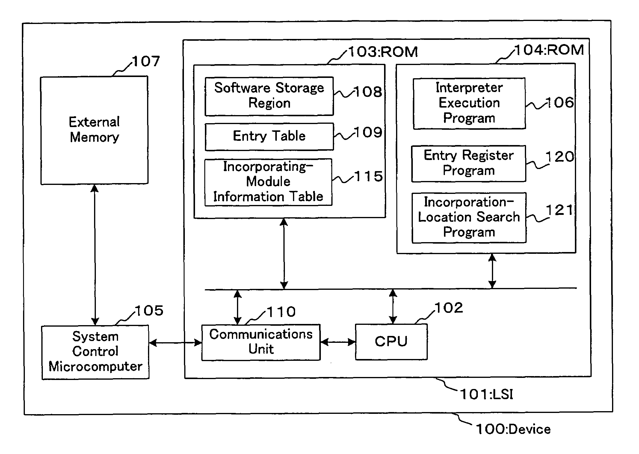
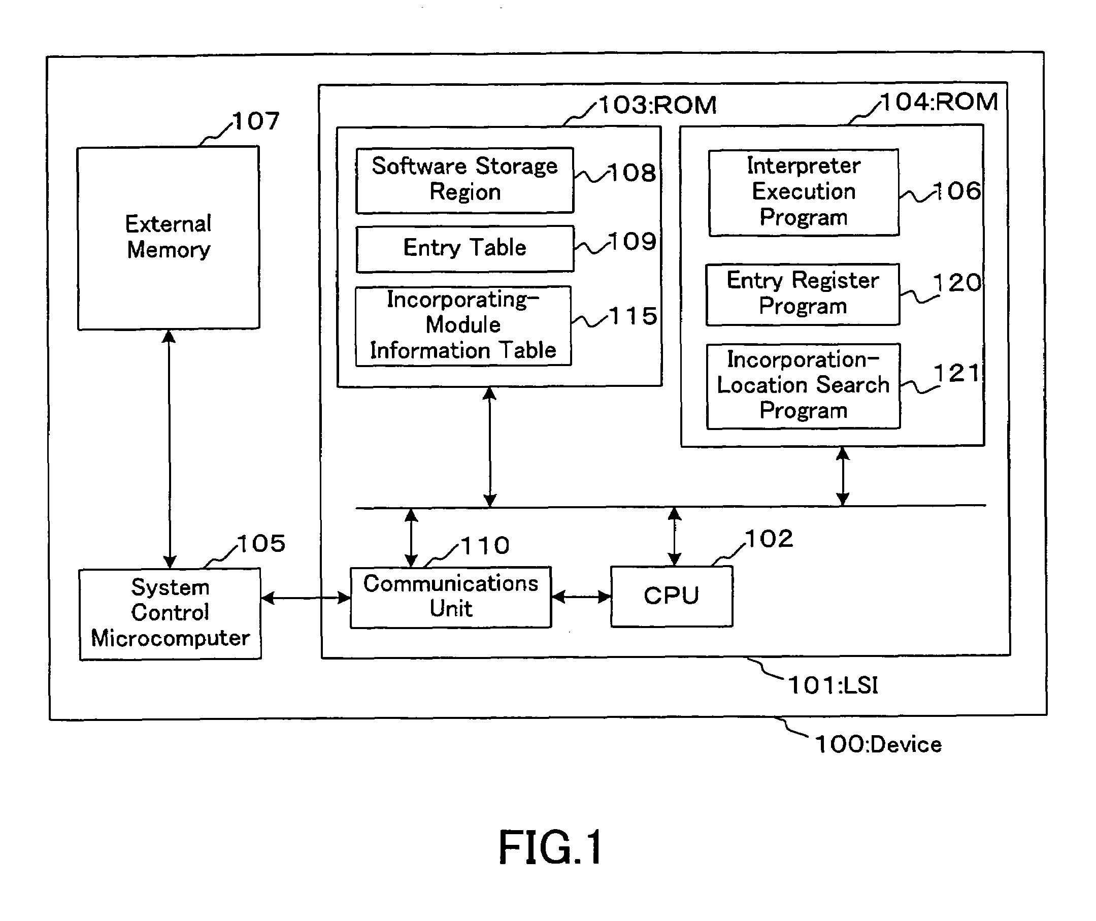
[0055]Embodiment 1 of the present invention is described below with reference to the drawings. FIG. 1 shows the configuration of a device according to the present embodiment, which is described below. Numeral 100 indicates a device according to the present embodiment. Numeral 101 denotes an LSI according to the present embodiment. Numeral 102 denotes a CPU that controls the LSI 101. Numeral 107 denotes an external memory in which software to be stored in a RAM 103, a program to be executed by a system control microcomputer 105, etc. are stored.
[0056]The RAM 103 can be accessed from the outside and includes at least the following three: 1) a software storage region, which is indicated with numeral 108, where software is to be stored, with the software being composed of an instruction sequence that is independent of the CPU and including a plurality of modules; 2) a table including entries (hereinafter, referred to as an “entry table”), which is indicated with numeral 109, where an entry denotes a set of data including at least a module initial address and module size of the software stored in the software storage region 108 (hereinafter, referred to simply as a “module”); and 3) a table (hereinafter, referred to as an “incorporating-module information table”), which is indicated with numeral 115, in which the name of a module to be newly incorporated into the RAM 103 from the external memory 107 (hereinafter, the module is referred to as an “incorporating module”), the size of the incorporating module, and the name of a module that has been stored in the RAM 103 but is no longer necessary after being executed once (hereinafter, the module is referred to as an “unnecessary module”) are stored.
[0057]Numeral 104 denotes a ROM that stores the following three programs: 1) an interpreter execution program, which is indicated with numeral 106, that interprets the software stored in the software storage region 108 to execute it; 2) an entry register program, which is indicated with numeral 120, that registers the entry of an incorporating module in the entry table 109; and 3) an incorporation-location search program, which is indicated with numeral 121, that makes a comparison between the size of an entry registered in the entry table 109 and the size of an incorporating module, and judges whether the module registered in the entry table 109 is unnecessary and whether the entry registered in the entry table 109 is the last one registered in the entry table 109 (hereinafter, the last entry registered in the entry table 109 is referred to as a “last entry”).
[0058]Numeral 110 indicates a communications unit used for communications between the LSI 101 and external units, and numeral 105 a system control microcomputer that controls the device 100 as a whole. The CPU 102 and both the RAM 103 and the ROM 104 as well as the external memory 107 and the system control microcomputer 105 are connected to each other through a bus, respectively. The system control microcomputer 105 can access the CPU 102 and the RAM 103 through the communications unit 110.
[0059]Next, the operation of the device 100 according to the present embodiment is described with reference to FIG. 1.
[0060]First, the system control microcomputer 105 incorporates, into the RAM 103, modules of software stored in the external memory 107. When the system control microcomputer 105 issues an interpreter execution command to the CPU 102, the CPU 102 executes the interpreter execution program 106 stored in the ROM 104. Thus the CPU 102 interprets the module incorporated into the RAM 103 to execute it.
[0061]FIGS. 2A, 2B, 3A, and 3B show the configurations of modules of software stored in the external memory 107 and the module storage status of the RAM 103. Numerals 201 to 206 indicate modules. The descriptions of parts indicated in FIGS. 2A, 2B, 3A, and 3B with the same numerals as those used in FIG. 1 are not repeated.
[0062]FIG. 4 shows a procedure for incorporating, into the RAM 103, an arbitrary module of the software stored in the external memory 107. FIGS. 5A to 5D show transitions in the entry table 109 that result from the incorporation, into the RAM 103, of the arbitrary one of the modules of the software stored in the external memory 107. As shown in FIGS. 5A to 5D, an entry consists of a registration no., a module name, a module initial address, and a module size. In FIGS. 5A to 5D, all the numerical values are indicated by the decimal numeral, and the unit of the module sizes indicated therein is kilobyte.
[0063]In the below, a specific example of the procedure for incorporating, into the RAM 103, an incorporating module 205 of the software stored in the external memory 107 is described with reference to FIGS. 1 to 5D. In this case, suppose the module storage status of the RAM 103 is that shown in FIG. 2A and the entry table 109 is that shown in FIG. 5A. Furthermore, a module 202 and a module 204 are unnecessary modules and the size of the incorporating module 205 is 300 kilobytes.
[0064]As shown in FIG. 4, at Step 301, when the system control microcomputer 105 issues an incorporating-module information storage command to the CPU 102, the CPU 102 allows the RAM 103 to store the name of the incorporating module (the module 205), the size of the incorporating module (300 kilobytes), and the names of unnecessary modules (the modules 202 and 204) in the incorporating-module information table 115.
[0065]Subsequently, at Step 302, when the system control microcomputer 105 issues a module incorporation-location search command to the CPU 102, the CPU 102 executes the incorporation-location search program 121. With respect to any one of the entries registered in the entry table 109, the CPU 102 judges from the information of the incorporating-module information table 115 whether the module is unnecessary (hereinafter, an entry subjected to the judgement is referred to as a “target entry”). When Step 302 is executed for the first time, the target entry is the entry whose registration no. is 1. In this case, since the module 201 of the target entry is to be executed successively in the device 100 (i.e. is not unnecessary one), the process proceeds to Step 309.
[0066]At Step 309, when the system control microcomputer 105 issues a module incorporation-location search command to the CPU 102, the CPU 102 executes the incorporation-location search program 121. The CPU 102 then judges from the entry table 109 whether the target entry is the last entry. In this case, since the target entry No. 1 is not the last entry, the process proceeds to Step 303.
[0067]At Step 303, the target entry is changed to another one. The change is made by a method in which the entry registered next to the current target entry in the entry table 109 is taken as a new target entry. That is, when the current target entry is No. 1, the target entry after the change is No. 2. After the change of the target entry, Step 302 is executed again. At Step 302, since the module 202 of the target entry No. 2 is an unnecessary one, the process proceeds to Step 304.
[0068]At Step 304, when the system control microcomputer 105 issues a module incorporation-location search command to the CPU 102, the CPU 102 executes the incorporation-location search program 121. The CPU 102 obtains the size of the incorporating module 205 from the information of the incorporating-module information table 115 and the size of the module of the target entry from the entry table 109 and then makes a comparison between the size of the incorporating module 205 and that of the module of the target entry. In this case, the size of the incorporating module 205 is 300 kilobytes, and the size of the module of the target entry is 200 kilobytes, i.e. the size of the module of the target entry is smaller than that of the incorporating module 205. Hence, in order to check whether the incorporating module 205 can be incorporated into the region of the RAM 103 where the module 202 has been stored, the process proceeds to Step 310.
[0069]At Step 310, when the system control microcomputer 105 issues a module incorporation-location search command to the CPU 102, the CPU 102 executes the incorporation-location search program 121. The CPU 102 then judges whether the target entry is the last entry. It is judged from the entry table 109 that the target entry No. 2 is not the last entry. Hence, in order to check whether the module of the entry registered next to the current target entry is an unnecessary one, the process proceeds to Step 305.
[0070]At Step 305, when the system control microcomputer 105 issues a module incorporation-location search command to the CPU 102, the CPU 102 executes the incorporation-location search program 121. The CPU 102 then judges from the information of the incorporating-module information table 115 whether the module of the entry registered next to the target entry is an unnecessary one. According to the entry table 109, the entry registered next to the target entry No. 2 is the entry No. 3. From the information of the incorporating-module information table 115, it is judged by the CPU 102 that a module 203 that is the module of the entry No. 3 is one to be executed successively in the device 100. Accordingly, the incorporating module 205 cannot be incorporated into the area of the RAM 103 where the module 202 has been stored. Consequently, the process proceeds to Step 303. After the target entry is changed from No. 2 to No.3, the process proceeds to Step 302 again. At Step 302, it is judged that the module 203 of the target entry No. 3 is one to be executed successively in the device 100. Accordingly, the process proceeds to Step 309.
[0071]At Step 309, since the target entry No. 3 is not the last entry, the target entry is changed from No. 3 to No. 4 at Step 303 and then the process proceeds to Step 302 once again. At Step 302, it is judged that the module 204 of the target entry No. 4 is an unnecessary one. Accordingly, the process proceeds to Step 304. Since the size of the module 204 of the target entry No. 4 is 500 kilobytes and that of the incorporating module 205 is 300 kilobytes, it is judged at Step 304 that the size of the module of the target entry is larger than that of the incorporating module 205. Consequently, the process proceeds to Step 307.
[0072]At Step 307, the CPU 102 notifies the system control microcomputer 105 about the initial address from which the incorporating module 205 is to be incorporated in the RAM 103, through the communications unit 110. In this case, the initial address from which the incorporating module 205 is to be incorporated in the RAM 103 is the initial address (700) of the module of the target entry. The system control microcomputer 105 incorporates the incorporating module 205 from the external memory 107 into the RAM 103 through the communications unit 110, with the module being incorporated from the initial address (700).
[0073]With this incorporation, the module storage status of the RAM 103 changes from that shown in FIG. 2A to that shown in FIG. 2B.
[0074]Next, at Step 308, when the system control microcomputer 105 issues an entry register command to the CPU 102, the CPU 102 executes the entry register program 120. The CPU 102 then additionally registers the entry of the incorporating module 205 in the entry table 109. With this register, the status of the entry table 109 changes from that shown in FIG. 5A to that shown in FIG. 5B.
[0075]With the procedure described above, the module 205 of the external memory 107 can be incorporated into the RAM 103.
[0076]The following description is made with reference to FIGS. 1 to 5D and is directed to another specific example of the procedure for incorporating the incorporating module 205 of the software stored in the external memory 107 into the RAM 103. In this example, suppose the module storage status of the RAM 103 is that shown in FIG. 2A and the entry table 109 is shown in FIG. 5A. In this case, the modules 202 and 203 are unnecessary modules and the size of the incorporating module 205 is 300 kilobytes.
[0077]At Step 301, the CPU 102 allows the RAM 103 to store the name of the incorporating module (the module 205), the size of the incorporating module 205 (300 kilobytes), and the names of unnecessary modules (the modules 202 and 203) in the incorporating-module information table 115.
[0078]Subsequently, at Step 302, the CPU 102 judges whether the module 201 of the target entry is unnecessary. In this case, since the module 201 of the target entry is to be executed successively in the device 100, the process proceeds to Step 309.
[0079]At Step 309, the CPU 102 judges whether the target entry is the last entry. In this case, since the target entry No. 1 is not the last entry, the process proceeds to Step 303.
[0080]At Step 303, the target entry is changed to No. 2, and Step 302 then is executed again. At Step 302, the CPU 102 judges that the module 202 of the target entry No. 2 is an unnecessary one, and then the process proceeds to Step 304.
[0081]At Step 304, the CPU 102 makes a comparison between the size of the incorporating module and that of the module of the target entry. In this case, the size of the module of the target entry is 200 kilobytes and the size of the incorporating module 205 is 300 kilobytes, i.e. the size of the module of the target entry is smaller than that of the incorporating module 205. Hence, in order to check whether the incorporating module 205 can be incorporated into the area of the RAM 103 where the module 202 has been stored, the process proceeds to Step 310.
[0082]At Step 310, the CPU 102 then judges whether the target entry is the last entry. The target entry No. 2 is not the last entry. Hence, in order to check whether the module of the entry registered next to the current target entry is an unnecessary one, the process proceeds to Step 305.
[0083]At Step 305, the CPU 102 judges whether the module 203 of the entry registered next to the target entry is an unnecessary one. It is judged from the entry table 109 that the entry registered next to the target entry No. 2 is the entry No. 3. The module 203 that is the module of the entry No. 3 is an unnecessary one. Hence, in order to check whether the incorporating module 205 can be incorporated into the areas of the RAM 103 where the modules 202 and 203 have been stored, the process proceeds to Step 306.
[0084]At Step 306, when the system control microcomputer 105 issues a module incorporation-location search command to the CPU 102, the CPU 102 executes the incorporation-location search program 121. The CPU 102 then makes a comparison between the size of the incorporating module 205 and the sum of the sizes of the module of the target entry No. 2 and the module of the entry No. 3 registered next thereto. In this case, according to the entry table 109, the size of the module of the target entry No. 2 is 200 kilobytes and that of the module of the entry No. 3 registered next thereto is 400 kilobytes, i.e. the sum of them is 600 kilobytes. On the other hand, according to the information of the incorporating-module information table 115, the size of the incorporating module 205 is 300 kilobytes. That is, the sum of the sizes of the modules of the target entry and the entry registered next thereto is larger than the size of the incorporating module 205. Accordingly, the incorporating module 205 can be incorporated into the areas of the RAM 103 where the modules 202 and 203 have been stored, and thus the process proceeds to Step 307.
[0085]At Step 307, the CPU 102 notifies the system control microcomputer 105 about the initial address from which the incorporating module 205 is to be incorporated in the RAM 103, through the communications unit 110. In this case, the initial address from which the incorporating module 205 is to be incorporated in the RAM 103 is the initial address (100) of the module of the target entry (the module 202). The system control microcomputer 105 incorporates the incorporating module 205 from the external memory 107 into the RAM 103 through the communications unit 110, with the incorporating module 205 being incorporated from the initial address (100). With this incorporation, the module storage status of the RAM 103 changes from that shown in FIG. 2A to that shown in FIG. 3A.
[0086]Next, at Step 308, the CPU 102 additionally registers the entry of the incorporating module 205 in the entry table 109. With this registration, the status of the entry table 109 changes from that shown in FIG. 5A to that shown in FIG. 5C.
[0087]With the procedure described above, the module 205 of the external memory 107 can be incorporated into the RAM 103.
[0088]The following description is made with reference to FIGS. 1 to 5D and is directed to still another specific example of the procedure for incorporating the incorporating module 205 of the software stored in the external memory 107 into the RAM 103. In this example, suppose the module storage status of the RAM 103 is that shown in FIG. 2A and the status of the entry table 109 is that shown in FIG. 5A. In this case, no unnecessary module is present in the RAM 103 and the size of the incorporating module 205 is 300 kilobytes.
[0089]At Step 301, the CPU 102 allows the RAM 103 to store the name of the incorporating module (the module 205), the size of the incorporating module (300 kilobytes), and the names of unnecessary modules (none in this case) in the incorporating-module information table 115.
[0090]Subsequently, at Step 302, the CPU 102 judges whether the module of the target entry is unnecessary one. In this case, since the module 201 of the target entry is to be executed successively in the device 100, the process proceeds to Step 309.
[0091]At Step 309, the CPU 102 judges whether the target entry is the last entry. In this case, since the target entry No. 1 is not the last entry, the process proceeds to Step 303.
[0092]At Step 303, the target entry is changed to No. 2, and Step 302 then is executed again. At Step 302, the CPU 102 judges that the module 202 of the target entry is to be executed successively in the device 100. Accordingly, the process proceeds to Step 309. At Step 309, the CPU 102 judges that the target entry is not the last entry. Accordingly, the process proceeds to Step 303. At Step 303, the target entry is changed to No. 3, and Step 302 then is executed once again. At Step 302, the CPU 102 judges that the module 203 of the target entry is to be executed successively in the device 100. Accordingly, the process proceeds to Step 309.
[0093]At Step 309, the CPU 102 judges that the target entry is not the last entry. Accordingly, the process proceeds to Step 303. At Step 303, the target entry is changed to No. 4, and Step 302 then is executed once again. At Step 302, the CPU 102 judges that the module 204 of the target entry is to be executed successively in the device 100. Accordingly, the process proceeds to Step 309.
[0094]At Step 309, it is judged that the target entry No. 4 is the last entry. Accordingly, the process proceeds to Step 311. The location in the RAM 103 where the incorporating module 205 is to be incorporated is after the module 204 of the last entry (i.e. 1200).
[0095]At Step 311, the CPU 102 notifies the system control microcomputer 105 about the initial address from which the incorporating module 205 is to be incorporated in the RAM 103, through the communications unit 110. In this case, the initial address from which the incorporating module 205 is to be incorporated in the RAM 103 is 1200, which indicates the location after the module 204 of the last entry. The system control microcomputer 105 incorporates the incorporating module 205 from the external memory 107 into the RAM 103 through the communications unit 110, with the incorporating module 205 being incorporated from the initial address (1200). With this incorporation, the module storage status of the RAM 103 changes from that shown in FIG. 2A to that shown in FIG. 3B. Subsequently, the process proceeds to Step 308. The CPU 102 then additionally registers the entry of the incorporating module 205 in the entry table 109, and thereby the status of the entry table 109 changes from that shown in FIG. 5A to that shown in FIG. 5D.
[0096]With the procedure described above, the module 205 of the external memory 107 can be incorporated into the RAM 103.

Example

Embodiment 2
[0097]Hereinafter, Embodiment 2 of the present invention is described with reference to the drawings. FIG. 6 shows the configuration of a device according to the present embodiment. As shown in FIG. 6, in the device according to the present embodiment, a program 122 is added to the ROM 104 of the device according to Embodiment 1. The program 122 is a program for erasing, from the entry table 109, an entry of an unnecessary module to be erased from the RAM 103.
[0098]With respect to the operation of the device according to the present embodiment, descriptions of the same parts as those in the device according to Embodiment 1 are not repeated herein. FIGS. 7A, 7B, 8A, and 8B show the configurations of modules of software stored in the external memory 107 and the module storage status of the RAM 103. Numerals 601 to 606 indicate modules. The descriptions of the parts shown in FIGS. 7A, 7B, 8A, and 8B and indicated with the same reference numbers as those used in FIG. 6 are not repeated herein. FIG. 9 shows the procedure for incorporating, into the RAM 103, an arbitrary module of the software stored in the external memory 107. FIGS. 10A to 10E show transitions in the entry table 109 that result from the incorporation, into the RAM 103, of the arbitrary module of the software stored in the external memory 107. The entry includes a registration no., a module name, a module initial address, and a module size. In FIGS. 10A to 10E, all the numerical values are indicated by the decimal numeral, and the unit of the module size is kilobyte.
[0099]In the below, a specific example of the procedure for incorporating, into the RAM 103, an incorporating module 605 of the software stored in the external memory 107 is described with reference to FIGS. 6 to 10E. In this case, suppose the module storage status of the RAM 103 is that shown in FIG. 7A and the status of the entry table 109 is that shown in FIG. 10A. Furthermore, modules 602 and 604 are unnecessary modules, and the size of the incorporating module 605 is 300 kilobytes.
[0100]At Step 701, when the system control microcomputer 105 issues an incorporating-module information storage command to the CPU 102, the CPU 102 allows the RAM 103 to store the name of the incorporating module (the module 605), the size of the incorporating module (300 kilobytes), and the names of unnecessary modules (the modules 602 and 604) in the incorporating-module information table 115.
[0101]Subsequently, at Step 702, when the system control microcomputer 105 issues a module incorporation-location search command to the CPU 102, the CPU 102 executes the incorporation-location search program 121. The CPU 102 judges from the information of the incorporating-module information table 115 whether the module of the target entry is an unnecessary one. When Step 702 is executed for the first time, the target entry is the entry whose registration No. is 1. In this case, since the module 601 of the target entry is to be executed successively in the device 100, the process proceeds to Step 703.
[0102]At Step 703, when the system control microcomputer 105 issues a module incorporation-location search command to the CPU 102, the CPU 102 executes the incorporation-location search program 121. The CPU 102 then judges from the entry table 109 whether the target entry is the last entry. In this case, since the target entry No. 1 is not the last entry, the process proceeds to Step 704.
[0103]At Step 704, the target entry is changed to another one. The change is made by a method in which the entry registered next to the current target entry in the entry table 109 is taken as a new target entry. That is, when the current target entry is No. 1, the target entry after the change is No. 2. After the change of the target entry, Step 702 is executed again. At Step 702, it is judged that the module 602 of the target entry No. 2 is unnecessary one. Accordingly, the process proceeds to Step 707.
[0104]At Step 707, when the system control microcomputer 105 issues an entry erasing command to the CPU 102, the CPU 102 executes the entry erasing program 122. The CPU 102 then erases, from the entry table 109, the target entry No. 2 and those registered after the target entry, i.e. the entries Nos. 2, 3, and 4, of the entries registered in the entry table 109. With this erasure, the status of the entry table 109 changes from that shown in FIG. 10A to that shown in FIG. 10B.
[0105]Next, at Step 708, the CPU 102 notifies the system control microcomputer 105 about the initial address from which the incorporating module 605 is to be incorporated in the RAM 103, through the communications unit 110. In this case, since the incorporating module 605 is to be incorporated into the area where the module 602 of the target entry that is an unnecessary one has been stored, the initial address (100) of the target entry is used as the initial address of the incorporating module 605. The system control microcomputer 105 incorporates the incorporating module 605 from the external memory 107 into the RAM 103 through the communications unit 110, with the incorporating module 605 being incorporated from the initial address (100). With this incorporation, the module storage status of the RAM 103 changes from that shown in FIG. 7A to that shown in FIG. 7B.
[0106]Next, at Step 709, when the system control microcomputer 105 issues an entry register command to the CPU 102, the CPU 102 executes the entry register program 120. The CPU 102 additionally registers the entry of the incorporating module 605 in the entry table 109. With this register, the status of the entry table 109 changes from that shown in FIG. 10B to that shown in FIG. 10C. The process then proceeds to Step 710 and thereby the target entry is changed to another one. Subsequently, the process proceeds to Step 711. When the current target entry is No. 2, the target entry after the change is the entry No. 3.
[0107]At Step 711, when the system control microcomputer 105 issues a module incorporation-location search command to the CPU 102, the CPU 102 executes the incorporation-location search program 121. The CPU 102 then judges from the information of the incorporating-module information table 115 whether the module of the target entry is an unnecessary one. Since the module 603 of the target entry is to be executed successively in the device 100, it is required to be incorporated into the RAM 103 once again. Accordingly, the process proceeds to Step 712.
[0108]At Step 712, the CPU 102 notifies the system control microcomputer 105 about the initial address from which the incorporating module 603 is to be incorporated in the RAM 103, through the communications unit 110. In this case, since the module 603 is to be incorporated after the module 605 of the last entry, the initial address from which the module 603 is to be incorporated in the RAM 103 is indicated with the value obtained through an addition of the module size (300 kilobytes) of the last entry to the module initial address (100) of the last entry, i.e. 400. The system control microcomputer 105 incorporates the module 603 from the external memory 107 into the RAM 103 through the communications unit 110, with the module 603 being incorporated from the initial address 1200. With this incorporation, the module storage status of the RAM 103 changes from that shown in FIG. 7B to that shown in FIG. 8A. Subsequently, the process proceeds to Step 713. When the system control microcomputer 105 issues an entry register command to the CPU 102, the CPU 102 executes the entry register program 120. The CPU 102 additionally registers the entry of the module 603 in the entry table 109. With this registration, the status of the entry table 109 changes from that shown in FIG. 10C to that shown in FIG. 10D.
[0109]Next, at Step 714, when the system control microcomputer 105 issues a module incorporation-location search command to the CPU 102, the CPU 102 executes the incorporation-location search program 121. The CPU 102 then judges from the entry table 109 whether the target entry is the last entry. In this case, since the target entry No. 3 is not the last entry, the process proceeds to Step 710 and the target entry then is changed to another one. Subsequently, the process proceeds to Step 711. When the current target entry is No. 3, the target entry after the change is No. 4.
[0110]At Step 711, the CPU 102 judges from the information of the incorporating-module information table 115 whether the module of the target entry is an unnecessary one. Since the module 604 of the target entry is an unnecessary one, it is not required to be incorporated into the RAM 103 once again. Accordingly, the process proceeds to Step 714.
[0111]At Step 714, the CPU 102 judges from the entry table 109 whether the target entry is the last entry. In this case, since the target entry No. 4 is the last entry, the incorporation of the incorporating module 605 into the RAM 103 is completed.
[0112]With the procedure described above, the module 605 of the external memory 107 can be incorporated into the RAM 103.
[0113]The following description is made with reference to FIGS. 6 to 10E and is directed to another specific example of the procedure for incorporating the incorporating module 605 of the software stored in the external memory 107 into the RAM 103. In this example, suppose the module storage status of the RAM 103 is that shown in FIG. 7A and the status of the entry table 109 is that shown in FIG. 10A. In this case, no unnecessary module exists in the RAM 103, and the size of the incorporating module 605 is 300 kilobytes.
[0114]At Step 701, the CPU 102 allows the RAM 103 to store the name of the incorporating module (the module 605), the size of the incorporating module (300 kilobytes), and the names of unnecessary modules (none in this case) in the incorporating-module information table 115.
[0115]Subsequently, at Step 702, the CPU 102 judges whether the module of the target entry is an unnecessary one. In this case, since the module 601 of the target entry is to be executed successively in the device 100, the process proceeds to Step 703.
[0116]At Step 703, the CPU 102 judges whether the target entry is the last entry. In this case, since the target entry No. 1 is not the last entry, the process proceeds to Step 704.
[0117]At Step 704, the target entry is changed to No. 2, and Step 702 then is executed again. At Step 702, the CPU 102 judges that the module 602 of the target entry is to be executed successively in the device 100. Accordingly, the process proceeds to Step 703.
[0118]At Step 703, the CPU 102 judges that the target entry No. 2 is not the last entry. Accordingly, the process proceeds to Step 704. At Step 704, the target entry is changed to No. 3, and Step 702 then is executed once again. At Step 702, the CPU 102 judges that the module 603 of the target entry is to be executed successively in the device 100. Accordingly, the process proceeds to Step 703. At Step 703, the CPU 102 judges that the target entry No. 3 is not the last entry. Accordingly, the process proceeds to Step 704. At Step 704, the target entry is changed to No. 4, and Step 702 then is executed once again. At Step 702, the CPU 102 judges that the module 604 of the target entry is to be executed successively in the device 100. Accordingly, the process proceeds to Step 703. At Step 703, it is judged that the target entry No. 4 is the last entry. Accordingly, the process proceeds to Step 705.
[0119]At Step 705, the CPU 102 notifies the system control microcomputer 105 about the initial address from which the incorporating module 605 is to be incorporated in the RAM 103, through the communications unit 110. In this case, the initial address from which the incorporating module 605 is to be incorporated in the RAM 103 is 1200, which indicates the location after the module 604 of the last entry. The system control microcomputer 105 incorporates the incorporating module 605 from the external memory 107 into the RAM 103 through the communications unit 110, with the incorporating module 605 being incorporated from the initial address 1200. With this incorporation, the module storage status of the RAM 103 changes from that shown in FIG. 7A to that shown in FIG. 8B. Subsequently, the process proceeds to Step 706. At Step 706, when the system control microcomputer 105 issues an entry register command to the CPU 102, the CPU 102 executes the entry register program 120. The CPU 102 then additionally registers the entry of the incorporating module 605 in the entry table 109, and thereby the status of the entry table 109 changes from that shown in FIG. 10A to that shown in FIG. 10E.
[0120]With the procedure described above, the module 605 of the external memory 107 can be incorporated into the RAM 103.

Example

Embodiment 3
[0121]Hereinafter, Embodiment 3 of the present invention is described with reference to the drawings. FIG. 11 shows the configuration of a device according to the present embodiment. As shown in FIG. 11, in the device according to the present embodiment, the entry table 109 is deleted from and two tables and one region are added to the RAM 103 shown in FIG. 6 illustrating the configuration of the device according to Embodiment 2, and two programs are added to the ROM 104 shown in FIG. 6.
[0122]One of the tables to be added to the RAM 103 is a compressed-module entry table 131 including entries of modules that have been compressed (hereinafter referred to as “compressed modules”). The other is an execution-module entry table 130 including entries of modules that have been expanded so as to be executed (hereinafter, referred to as “execution modules”) after the compressed modules are interpreted with an interpreter execution program. The region added to the RAM 103 is a compressed-module storage region 132 where the compressed modules are stored.
[0123]One of the programs additionally included in the ROM 104 is a module compression program 123 for carrying out the process of compressing execution modules and then storing them in the compressed-module storage region. The other is a module expansion program 124 for carrying out the process of expanding the compressed modules included in the RAM 103 and then storing them in the software storage region 108. In this context, examples of general methods of compressing and expanding codes include Lempel-Ziv (LZ) compression and Huffman compression. Any compression-expansion methods can be used for compressing and expanding modules in the present invention.
[0124]With respect to the operation of the device according to the present embodiment, descriptions of the same parts as those in Embodiment 1 are not repeated herein. FIGS. 12A, 12B, 13A, and 13B show the configurations of modules of software stored in the external memory 107 and the module storage status of the RAM 103. Numerals 1001 to 1006 indicate modules. The descriptions of the parts shown in FIGS. 12A, 12B, 13A, and 13B and indicated with the same reference numbers as those used in FIG. 11 are not repeated herein. FIG. 14 shows the procedure for incorporating, into the RAM 103, an arbitrary module of the software stored in the external memory 107. FIGS. 15A to 15F and FIGS. 15G to 15I show transitions in the execution-module entry table 130 and the compressed-module entry table 131, respectively, which result from the incorporation of the arbitrary module of the software stored in the external memory 107 into the RAM 103. Both in the execution-module entry table 130 and the compressed-module entry table 131, the entry includes a registration no., a module name, a module initial address, and a module size. The sizes of the modules of entries included in the compressed-module entry table 131 are those of the modules that have not been compressed yet. In FIGS. 15A to 15I, all the numerical values are indicated by the decimal numeral, and the unit of the module size is kilobyte.
[0125]In the below, a specific example of the procedure for incorporating, into the RAM 103, an incorporating module 1005 of the software stored in the external memory 107 is described with reference to FIGS. 11 to 15I. In this case, suppose the module storage status of the RAM 103 is that shown in FIG. 12A, the status of the execution-module entry table 130 is that shown in FIG. 15A, and the status of the compressed-module entry table 131 is that shown in FIG. 15G. Furthermore, modules 1002 and 1004 are unnecessary modules, and the size of the incorporating module 1005 is 300 kilobytes.
[0126]At Step 1101, when the system control microcomputer 105 issues an incorporating-module information storage command to the CPU 102, the CPU 102 allows the RAM 103 to store the name of the incorporating module (the module 1005), the size of the incorporating module (300 kilobytes), and the names of unnecessary modules (the modules 1002 and 1004) in the incorporating-module information table 115.
[0127]Subsequently, at Step 1102, when the system control microcomputer 105 issues a module incorporation-location search command to the CPU 102, the CPU 102 executes the incorporation-location search program 121. The CPU 102 then judges from the information of the incorporating-module information table 115 whether the module of the target entry is an unnecessary one. When Step 1102 is executed for the first time, the target entry is the entry whose registration no. is 1. In this case, since the module 1001 of the target entry is to be executed successively in the device 100, it has to be stored in the compressed-module storage region after being compressed. Accordingly, the process proceeds to Step 1103.
[0128]At Step 1103, when the system control microcomputer 105 issues a module compression command to the CPU 102, the CPU 102 executes the module compression program 123. The CPU 102 compresses the module 1001 of the target entry and then stores it in the compressed-module storage region 132. With this storage, the module storage status of the RAM 103 changes from that shown in FIG. 12A to that shown in FIG. 12B. In FIG. 12B, numeral 1001′ denotes the compressed module of the module 1001.
[0129]Subsequently, at Step 1104, when the system control microcomputer 105 issues a compressed-module entry register command to the CPU 102, the CPU 102 executes the entry register program 120. The CPU 102 then additionally registers the entry of the compressed module 1001′ in the compressed-module entry table 131. With this registration, the status of the compressed-module entry table 131 changes from that shown in FIG. 15G to that shown in FIG. 15H.
[0130]Next, at Step 1106, when the system control microcomputer 105 issues a module incorporation-location search command to the CPU 102, the CPU 102 executes the incorporation-location search program 121. The CPU 102 then judges from the execution-module entry table 130 whether the target entry is the last entry. Since the entry whose registration no. is 1 is not the last entry, the process proceeds to Step 1105. At Step 1105, when the system control microcomputer 105 issues an entry erasing command to the CPU 102, the CPU 102 executes the entry erasing program 122. The CPU 102 then erases the target entry from the execution-module entry table 130. With this erasure, the status of the execution-module entry table 130 changes from that shown in FIG. 15A to that shown in FIG. 15B.
[0131]Subsequently, at Step 1107, the target entry is changed to another one. The change is made by a method in which the entry No. 1 listed in the execution-module entry table 130 is taken as a new target entry. After the change of the target entry, Step 1102 is executed again. At Step 1102, it is judged, from the information of the incorporating-module information table 115, that the module 1002 of the target entry No. 1 is unnecessary one. It therefore is not necessary to compress the module 1002 and then to store it in the compressed-module storage region. Accordingly, the process proceeds to Step 1106.
[0132]At Step 1106, the CPU 102 judges from the execution-module entry table 130 whether the target entry is the last entry. In this case, the target entry No. 1 is not the last entry. Accordingly, the process proceeds to Step 1105. At Step 1105, the CPU 102 erases the target entry from the execution-module entry table 130. With this erasure, the status of the execution-module entry table 130 changes from that shown in FIG. 15B to that shown in FIG. 15C.
[0133]Subsequently, at Step 1107, the target entry is changed to another one. The entry No. 1 listed in the execution-module entry table 130 is taken as a new target entry. After the change of the target entry, Step 1102 is executed once again. At Step 1102, the CPU 102 judges from the information of the incorporating-module information table 115 whether the module of the target entry is an unnecessary one. In this case, since the module 1003 of the target entry is to be executed successively in the device 100, it is necessary to compress the module 1003 and then to store it in the compressed-module storage region. Accordingly, the process proceeds to Step 1103. At Step 1103, the CPU 102 compresses the module 1003 of the target entry and then stores it in the compressed-module storage region 132. With this storage, the module storage status of the RAM 103 changes from that shown in FIG. 12B to that shown in FIG. 13A. In FIG. 13A, numeral 1003′ denotes the compressed module of the module 1003.
[0134]Next, at Step 1104, the CPU 102 additionally registers the entry of the compressed module 1003′ in the compressed-module entry table 131. With this registration, the status of the compressed-module entry table 131 changes from that shown in FIG. 15H to that shown in FIG. 15I.
[0135]Next, at Step 1106, the CPU 102 judges from the execution-module entry table 130 whether the target entry is the last entry. In this case, since the entry No. 1 is not the last entry, the process proceeds to Step 1105. At Step 1105, the CPU 102 erases the target entry from the execution-module entry table 130. With this erasure, the status of the execution-module entry table 130 changes from that shown in FIG. 15C to that shown in FIG. 15D.
[0136]Subsequently, at Step 1107, the target entry is changed to another one. The entry No. 1 listed in the execution-module entry table 130 is taken as a new target entry. After the change of the target entry, Step 1102 is executed once again. At Step 1102, it is judged that the module 1004 of the target entry No. 1 is an unnecessary one. Accordingly, the process proceeds to Step 1106.
[0137]At Step 1106, the CPU 102 judges from the execution-module entry table 130 whether the target entry is the last entry. In this case, the target entry No. 1 is the last entry. Accordingly, the process proceeds to Step 1110.
[0138]At Step 1110, the CPU 102 erases the target entry from the execution-module entry table 130. With this erasure, the status of the execution-module entry table 130 changes from that shown in FIG. 15D to that shown in FIG. 15E.
[0139]Next, at Step 1108, the CPU 102 notifies the system control microcomputer 105 about the initial address from which the incorporating module 1005 is to be incorporated in the RAM 103, through the communications unit 110. In this case, the initial address of the incorporating module 1005 is the initial address of the software storage region 108, i.e. 0. The system control microcomputer 105 incorporates the incorporating module 1005 from the external memory 107 into the RAM 103 through the communications unit 110, with the incorporating module 1005 being incorporated from the initial address 0. With this incorporation, the module storage status of the RAM 103 changes from that shown in FIG. 13A to that shown in FIG. 13B.
[0140]Subsequently, the process proceeds to Step 1109. At Step 1109, when the system control microcomputer 105 issues an entry register command to the CPU 102, the CPU 102 executes the entry register program 120. The CPU 102 then additionally registers the entry of the incorporating module 1005 in the execution-module entry table 130. With this registration, the status of the execution-module entry table changes from that shown in FIG. 15E to that shown in FIG. 15F.
[0141]When the system control microcomputer 105 issues a module expansion command to the CPU 102, the CPU 102 executes the module expansion program 124. The compressed modules 1001′ and 1003′ that have been compressed and then stored in the compressed-module storage region 132 and are to be executed successively in the device 100 are expanded in the software storage region 108. Like the execution-module entry table 130, the compressed-module entry table 131 is effective in managing the compressed modules.
[0142]According to the devices of Embodiments 1 to 3, since software can be stored on a module-by-module basis, modules to be executed in the devices can be stored in the RAM 103 at the times when they are required. Furthermore, the software also can be erased from the RAM 103 on a module-by-module basis. Hence, modules that are no longer necessary after being executed once can be erased from the RAM 103. Accordingly, the capacity of the RAM 103 to be used can be kept down to a minimum. Furthermore, it is not necessary to store, in the RAM 103, all the modules of the software stored in the external memory 107. Consequently, it is possible to develop optical disk devices without placing a limitation that the size of the software must not exceed that of the software region of the RAM 103 provided in the system.
[0143]According to the device of Embodiment 3, software is compressed and expanded inside the RAM 103 and thereby the capacity of the RAM 103 to be used can be kept down to a minimum. The specific example of the present embodiment described the configuration of the device in which software is incorporated into the RAM on a module-by-module basis and the compression and expansion also are carried out inside the RAM on a module-by-module basis. However, the unit that is subjected to the processes of incorporation into the RAM as well as compression and expansion inside the RAM is not limited to part of the software (for instance, on a module-by-module basis) but may be the entire software.

PUM

no PUM

Description & Claims & Application Information

We can also present the details of the Description, Claims and Application information to help users get a comprehensive understanding of the technical details of the patent, such as background art, summary of invention, brief description of drawings, description of embodiments, and other original content. On the other hand, users can also determine the specific scope of protection of the technology through the list of claims; as well as understand the changes in the life cycle of the technology with the presentation of the patent timeline. Login to view more.

Similar technology patents

Method for showing an instant notice on a display of computer according to an incoming event of a mobile device

InactiveUS20160216953A1memory capacity be reduce
Owner:I O INTERCONNECT INC

Apparatus and method for an additional contents display of an optical disc player

InactiveUSRE42441E1memory capacity be reduce
Owner:LG ELECTRONICS INC

Oscillation device

ActiveUS20130038397A1memory capacity be reduce
Owner:NIHON DEMPA KOGYO CO LTD

Decoding method and decoding apparatus

InactiveUS20070065024A1memory capacity be reduce
Owner:NTT MOBILE COMM NETWORK INC

Classification and recommendation of technical efficacy words

  • low power consumption
  • memory capacity be reduce

Display apparatus

ActiveUS20070273701A1memory capacity be reduce
Owner:GLOBAL OLED TECH

Semiconductor memory having variable memory size and method for refreshing the same

ActiveUS20050152200A1reduce capacitymemory capacity be reduce
Owner:SAMSUNG ELECTRONICS CO LTD

Oscillation device

ActiveUS20130038397A1memory capacity be reduce
Owner:NIHON DEMPA KOGYO CO LTD

Decoding method and decoding apparatus

InactiveUS20070065024A1memory capacity be reduce
Owner:NTT MOBILE COMM NETWORK INC
Why Eureka
Try Eureka