Optical packet switching system

a technology of optical packet switching and optical receiver, which is applied in the field of optical packet switching system, can solve the problems of wasting the bandwidth corresponding to the bandwidth and affecting the ability of optical receivers of network elements to properly receive optical packet signals

Inactive Publication Date: 2013-02-14
FUJITSU LTD
View PDF3 Cites 8 Cited by
  • Summary
  • Abstract
  • Description
  • Claims
  • Application Information

AI Technical Summary

Benefits of technology

[0010]Each of the transmitting network elements may adjust the light power and / or extinction ratio of the optical packet signal.
[0011]The difference information transmitter may set the average value of the OSNRs of all of the optical packet signals received within the predetermined time duration, to the target value.

Problems solved by technology

The IP packet does not transfer any significant information in the absence of data therein, so that the bandwidth corresponding thereto is wasted.
It is difficult for an optical receiver of a network element to properly receive the optical packet signals if the OSNR varies for each optical packet signal.

Method used


Image

  • Optical packet switching system
  • Optical packet switching system
  • Optical packet switching system

Examples


Embodiment Construction

[0029]The invention will now be described by reference to the preferred embodiments. This does not intend to limit the scope of the present invention, but to exemplify the invention.

[0030]Embodiments of the present invention will be hereinbelow described with reference to Drawings.

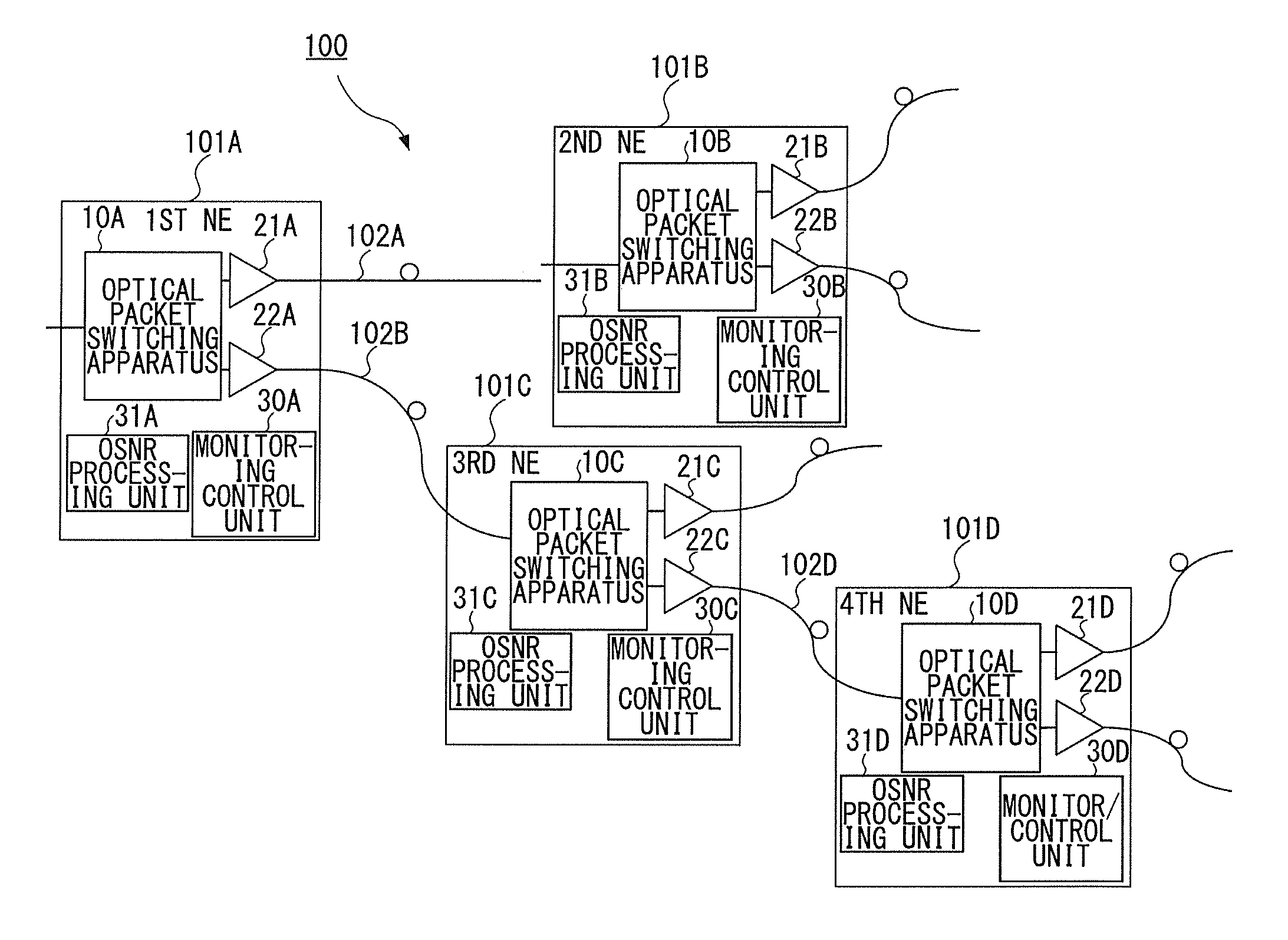
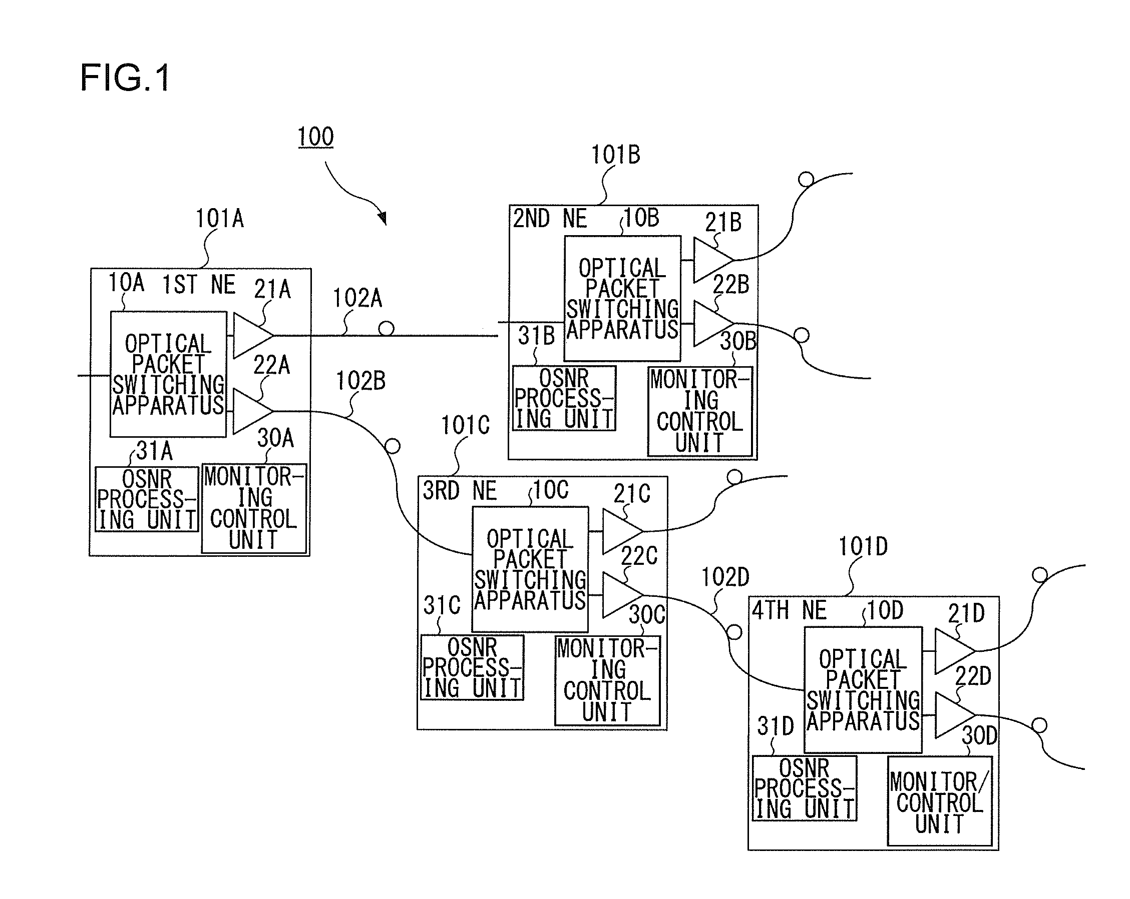
[0031]FIG. 1 is a diagram for explaining an optical packet switching system according to an embodiment of the present invention. As shown in FIG. 1, an optical packet switching system 100 includes first to fourth network elements (NEs) 101A to 101D. In the following description, the first to fourth network elements 101A to 101D may also be collectively or generically called “network element 101”. Though, in the present embodiment, the optical packet switching system 100 has four network elements, the optical packet switching system 100 may actually have an arbitrary number of network elements.

[0032]The first to fourth network elements 101A to 101D, which are connected by optical fibers, constitute an optic...


PUM


Abstract

An optical packet switching system includes a plurality of network elements for transmitting and receiving optical packet signals. Each network element includes an optical signal-to-noise ratio (OSNR) acquiring unit for acquiring the OSNR of each optical packet signal, an average value calculating unit for calculating the average value of the OSNRs of optical packet signals received within a predetermined time duration for each of the plurality of source network elements, and a difference information transmitter for calculating the difference between the calculated average value of the OSNRs and a target value of the OSNRs and then transmitting the difference to a network element corresponding to the difference. A source network element that has received the difference information adjusts the characteristics of an optical packet signal to be transmitted in a manner such that the difference is reduced.

Description

BACKGROUND OF THE INVENTION[0001]1. Field of the Invention[0002]The present invention relates to an optical packet switching system that enables packet switching for each optical packet.[0003]2. Description of the Related Art[0004]In optical transmission systems employing wavelength division multiplexing (WDM), a technique that performs the path switching per wavelength by the use of a wavelength selective switch (WSS) and the like is put to practical use. As a technology that may succeed this technique, an optical packet switching method is now being investigated. In this optical packet switching method, an IP packet (10 GEther (10 Gigabit Ethernet (registered trademark) signal and the like), for example, is used as a small unit with which the switching is performed, and each is converted into the form of an optical packet and then the route is switched by an ultrahigh-speed optical switch (see Reference (1) in the following Related Art List, for instance).[0005]The IP packet does ...

Claims


Application Information

Patent Timeline
Patent Type & Authority Applications(United States)
IPC IPC(8): H04B10/08H04Q11/00
CPCH04Q11/0005H04Q2011/0039H04J14/0275H04J14/0212H04Q2011/0049
Inventor SATO, REIKO
Owner FUJITSU LTD
Why Eureka
Try Eureka