

Touch-control type keyboard
a keyboard and touch control technology, applied in the field of keyboards, can solve the problems of difficult to further reduce the thickness of the keyboard, delay in the typing speed of the process, and much slower typing on the touch panel
- Summary
- Abstract
- Description
- Claims
- Application Information
AI Technical Summary
Benefits of technology
Problems solved by technology
Method used
Image

Examples
first embodiment
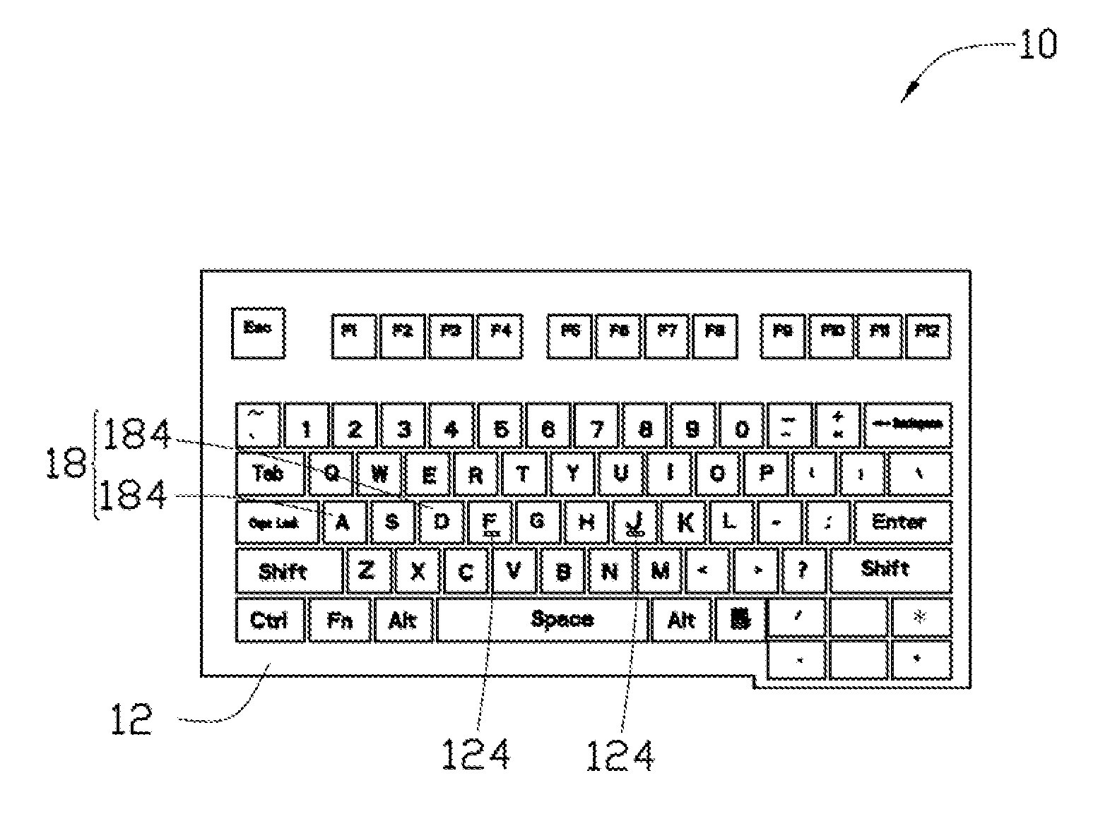
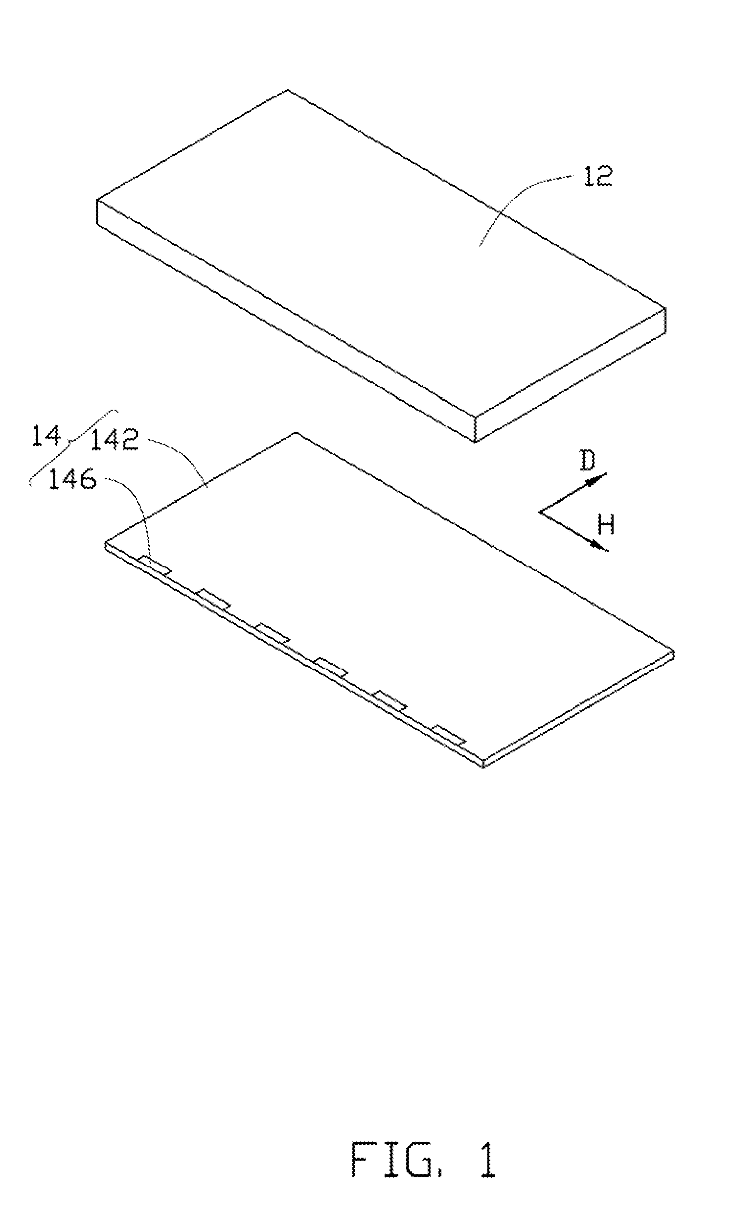
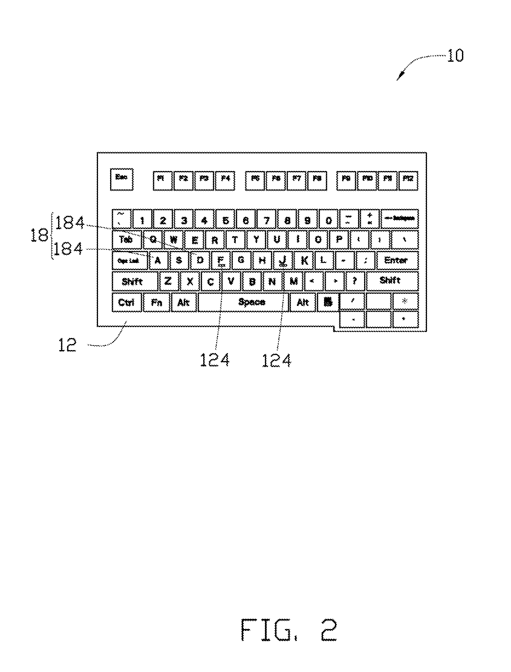
[0029]Referring to FIG. 1 and FIG. 2, a touch-control type keyboard 10 includes a transparent cover board 12 and a touch-control module 14. The transparent cover board 12 is stacked on the touch-control module 14.
[0030]In one embodiment, the touch-control type keyboard 10 can be arranged on a displaying surface of a display. The user can see the display through the touch-control type keyboard 10. In another embodiment, the touch-control type keyboard 10 can be separated from the display.
[0031]The transparent cover board 12 is an integrated plate shaped structure. The transparent cover board 12 covers the touch-control module 14, and is in contact and fixed on the touch-control module 14. The transparent cover board 12 has an outer surface nearest to the user. The outer surface an operating surface of the touch-control type keyboard 10 for the user. The outer surface may be continuous. Some regions of the outer surface of the transparent cover board 12 are defined as a plurality of k...
second embodiment
[0058]Referring to FIG. 7 and FIG. 8, a touch-control type keyboard 20 includes a transparent cover board 22 and a touch-control module 24. The transparent cover board 22 and the touch-control module 24 are laminated together. The transparent cover board 22 covers the touch-control module 24, and is in contact with the touch-control module 24. The outer surfaces of the transparent cover board 22 have a plurality of concave-convex structures 224 for the user to distinguish the positions of the keys. Each concave-convex structure 224 can be a convex having a hemispherical shape. Each convex corresponds to a key position. The outer surfaces of the transparent cover board 22 between two concave-convex structures 224 are relatively smooth and flat. The outer surfaces of the transparent cover board 22 have a plurality of concave-convex structures 224 are belonged to the tactual zone. The outer surfaces of the transparent cover board 22 between the plurality of concave-convex structures 22...
fourth embodiment
[0067]Referring to FIG. 10, a touch-control type keyboard 40 includes a transparent cover board 42 and a touch-control module 44. The transparent cover board 42 and the touch-control module 44 are laminated together. The transparent cover board 42 covers and contacts the touch-control module 44. The outer surfaces of the transparent cover board 42 have a plurality of concave-convex structures 424 for the user to distinguish the positions of the keys.
[0068]The structure of the fourth embodiment of the touch-control type keyboard 40 is similar to the third embodiment, except that the touch-control type keyboard 40 includes a keyboard marking sheet 48. The keyboard marking sheet 48 is free-standing and can be located between the transparent cover board 42 and the touch-control module 44, or between the backlight module 46 and the touch-control module 44. The keyboard marking sheet 48 includes a transparent sheet 482 and a keyboard marking layer 484 located on a surface of the transpare...
PUM
 Abstract
Description
Claims
Application Information