Positioning mechanism for a bicycle cooling device

Inactive Publication Date: 2013-02-28
ASHIMA LTD
View PDF3 Cites 0 Cited by
  • Summary
  • Abstract
  • Description
  • Claims
  • Application Information

AI Technical Summary

Benefits of technology

[0007]The main objective of the present invention

Problems solved by technology

If the braking action keeps working for a period of time, the brake disc and the brake pads are in the status of overheat and which will reduce the sens

Method used


Image

  • Positioning mechanism for a bicycle cooling device
  • Positioning mechanism for a bicycle cooling device
  • Positioning mechanism for a bicycle cooling device

Examples


Example

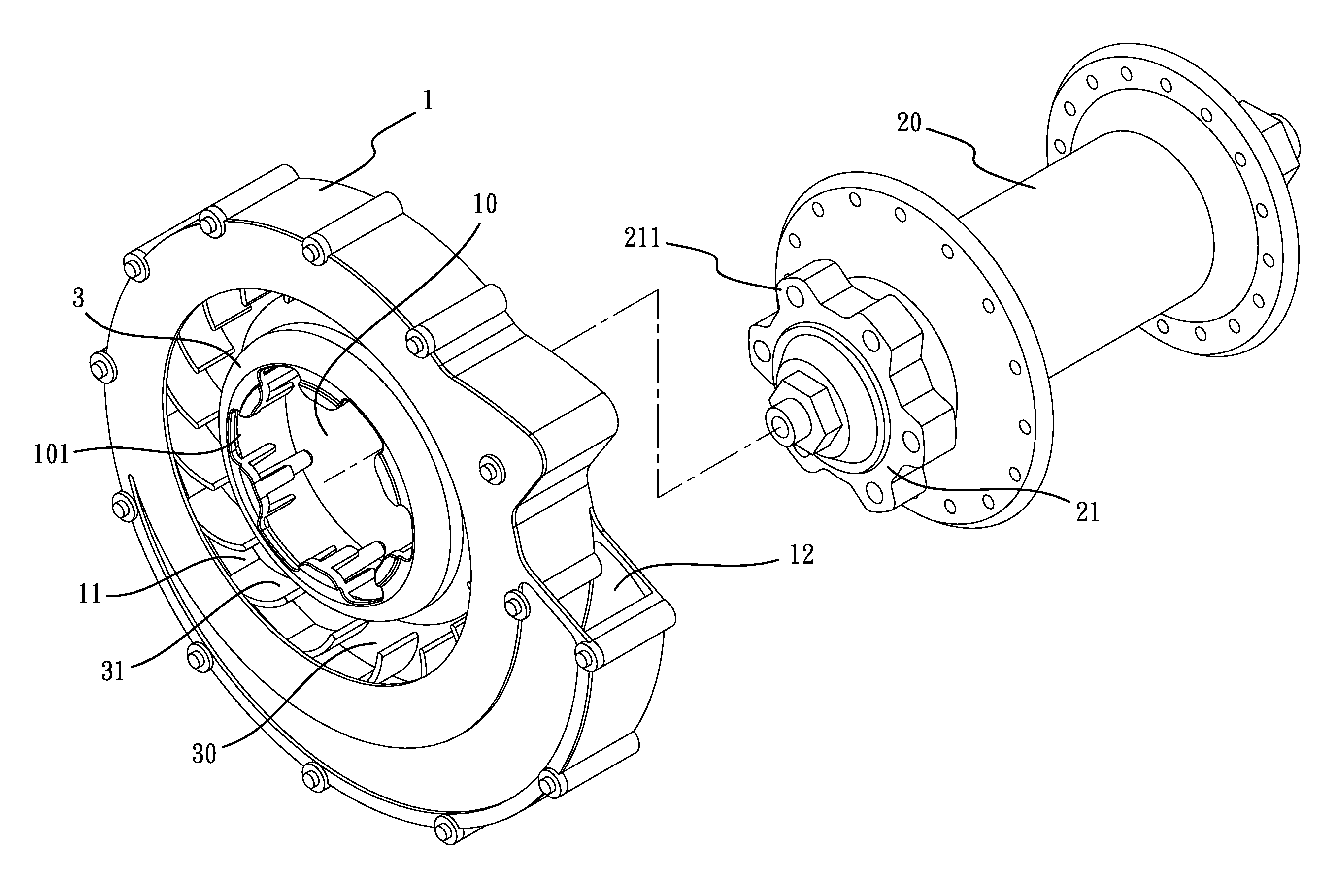
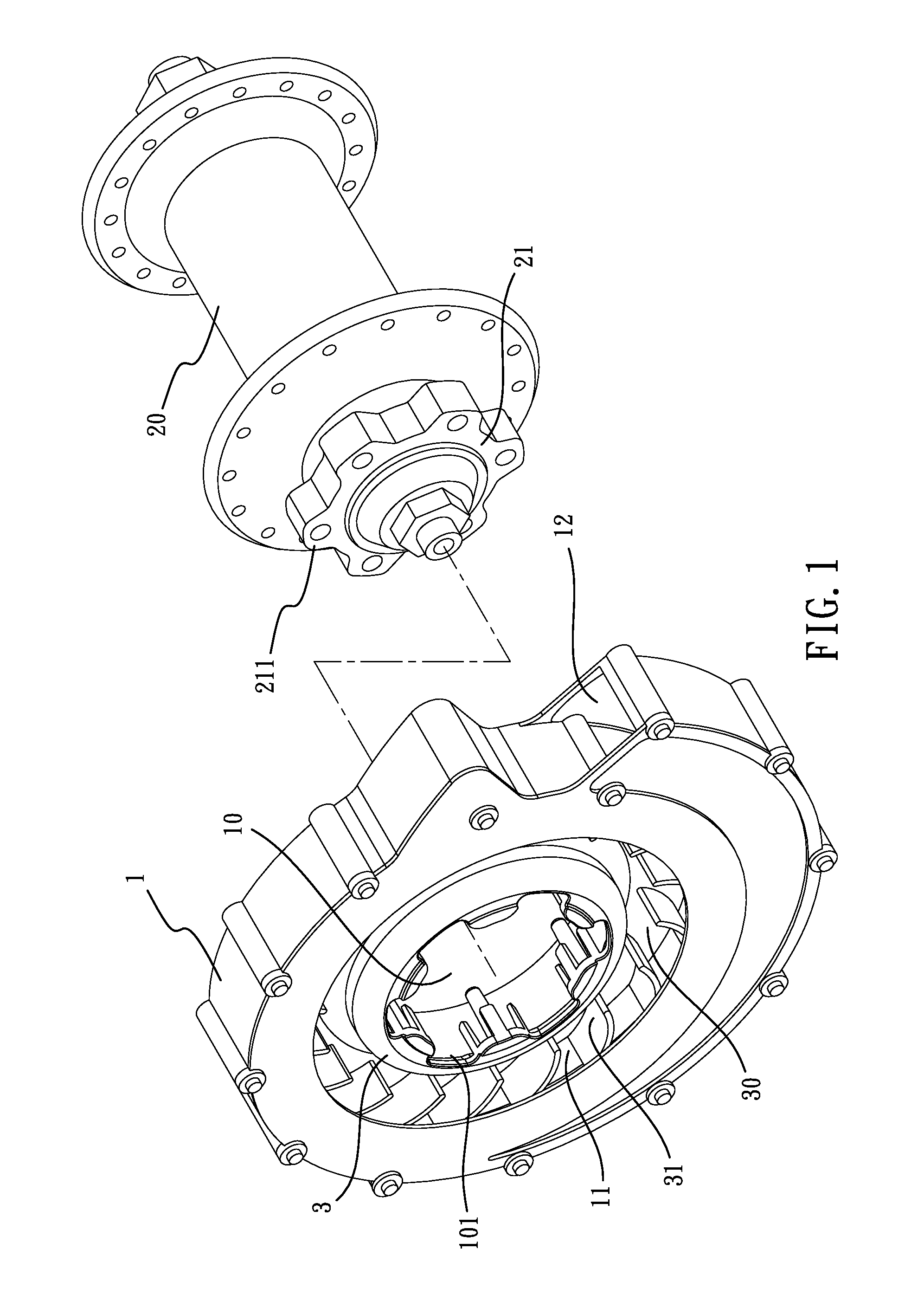
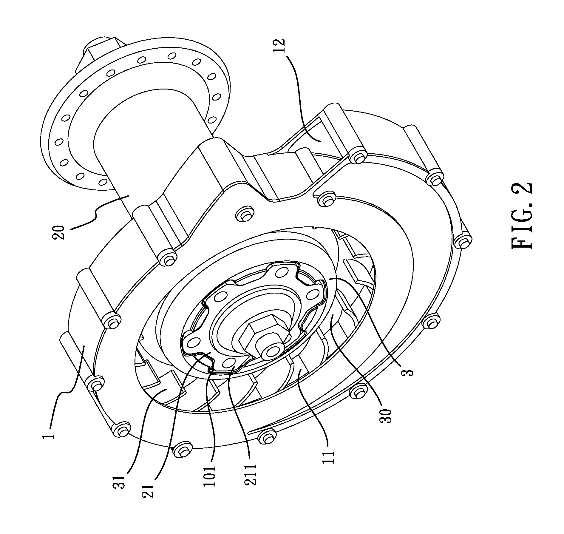
[0014]Referring to the drawings and initially to FIGS. 1 and 2, a positioning mechanism for a bicycle cooling device in accordance with the present invention under the first embodiment comprises a cooling device 1 and a ring 21. The cooling device 1 has a turbine unit 3 which has a positioning hole 10 defined in the center thereof. The turbine unit 3 has an annular groove 30 defined around the positioning hole 10 and multiple blades 31 are located around the annular groove 30. The blades 31 extend toward the positioning hole 10 so that when the turbine unit 3 is rotated in the cooling device 1, the annular groove 30 assists the thermo convection in the cooling device 1 by cooperating with the blades 31.

[0015]The cooling device 1 has a chamber 11 defined therein and the annular groove 30 is located in the chamber 11. The cooling device 1 has an exit 12 which communicates with the chamber 11. The turbine unit 3 has the positioning hole 10 at the center thereof and six recesses 101 are...


PUM


Abstract

A cooling device for bicycles includes a cooling device and a ring, wherein the cooling device has a positioning hole and multiple recesses are located around the positioning hole. The ring is connected to the hub and multiple protrusions are located on the periphery of the ring. The recesses are located corresponding to the protrusions which are engaged with the recesses to secure the cooling device to the ring.

Description

BACKGROUND OF THE INVENTION[0001]1. Field of the Invention[0002]The present invention relates to a positioning mechanism, and more particularly to a positioning mechanism for a bicycle cooling device.[0003]2. Description of Related Art[0004]There are two types of conventional bicycle braking systems, one of which is the V-type braking system and another is the brake-disc braking system. The two types of bicycle braking systems have different advantages. The V-type braking system moves the braking pads to contact the wheel rim by pulling braking cables so as to stop the wheel. The brake-disc braking system is operated by either hydraulic power or mechanical power, wherein the hydraulic power drives the clamps via the operation levers, and the mechanical power uses wires to connect the operation levers and the clamps. The brake pads in the clamps clamp the brake disc on the axle of the wheel so as to stop the wheel.[0005]When the brake pads in the clamps clamp the brake disc to stop t...

Claims


Application Information

Patent Timeline
IPC IPC(8): F16D65/847
CPCF16D65/847
Inventor MOORE, WAYNE-IAN
Owner ASHIMA LTD
Why Eureka
Try Eureka