
Intruder imaging and identification system

Inactive Publication Date: 2013-03-07
BARANEK JOHN
View PDF33 Cites 30 Cited by
  • Summary
  • Abstract
  • Description
  • Claims
  • Application Information

AI Technical Summary

Benefits of technology

The patent describes a device that captures images of intruders using a video camera. The camera can be placed at the entry way of a building or above a window. A recording device, like a memory card or flash card, can be used to store the captured images. The device is designed to work with smartphones or computer tablets, making it easy to set up and use. The technical effect of this device is to provide a convenient and effective way to capture images of intruders and securely store them for later use.

Problems solved by technology

The recording means is often located away from the video camera, since once discovered, an intruder will often destroy the camera in an attempt to destroy any recorded data.
However, a downfall of these and many other devices is that when the cameras are placed in plain sight, the intruder can simply avoid the locations of the camera as they approach a building or home.
Further, even if the cameras are hidden, if the intruder is moving quickly or purposefully averting their gaze, identifiable facial images are frequently difficult to capture, even with the use of facial recognition software.
Additionally, even if not hidden, the angle at which the photo is taken, will frequently only capture one side of the face, or simply not enough to provide a digital photo capable of identification by software.
However the device requires a user to activate the gaze attracting means and is therefor not suitable for unmanned and automated surveillance systems.
Various limitations of the related art will become apparent to those skilled in the art upon a reading and understanding of the specification below and the accompanying drawings.

Method used


Image

  • Intruder imaging and identification system
  • Intruder imaging and identification system
  • Intruder imaging and identification system

Examples


Embodiment Construction

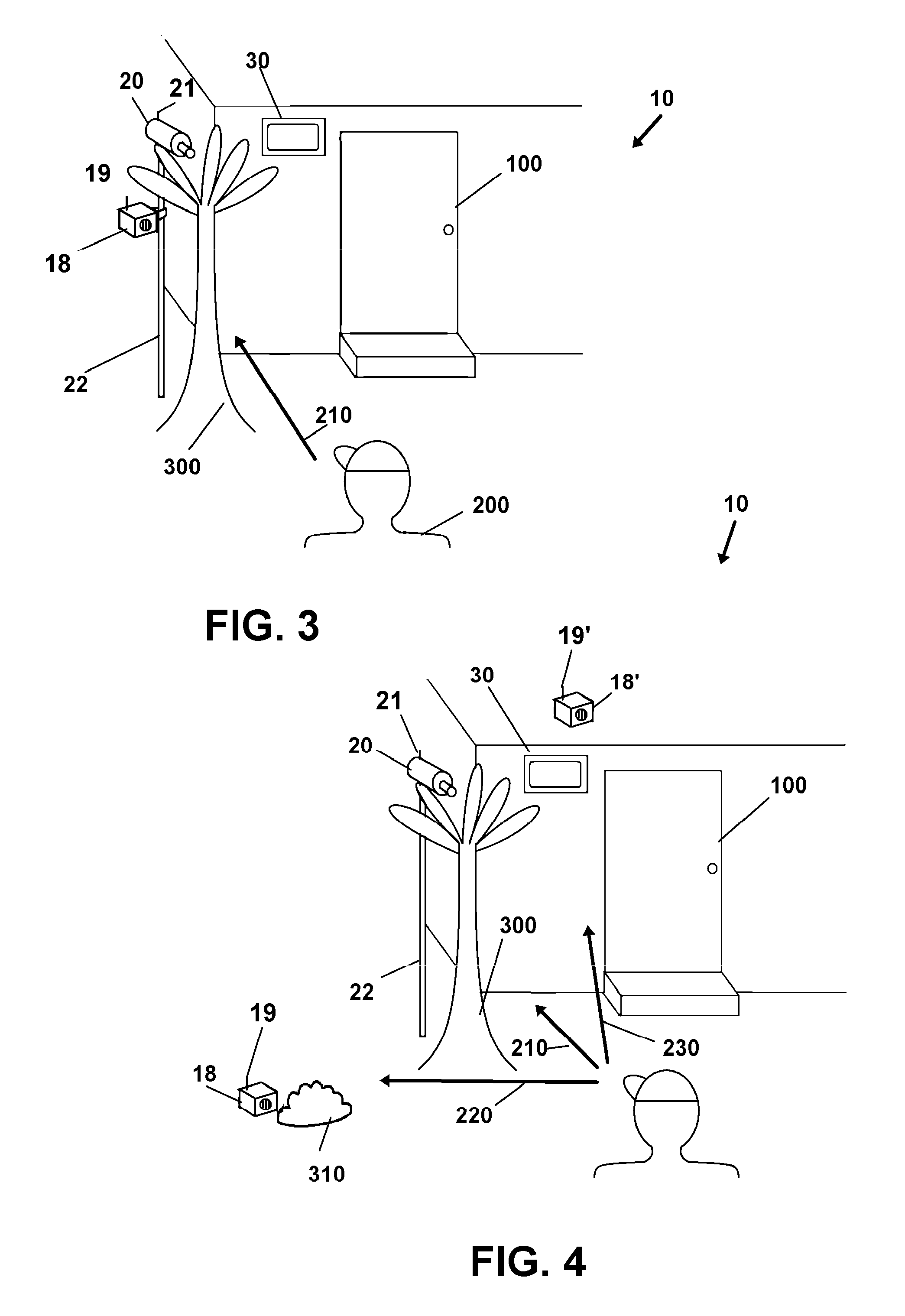
[0054]In this description, the directional prepositions of up, upwardly, down, downwardly, front, back, top, upper, bottom, lower, left, right and other such terms refer to the device as it is oriented and appears in the drawings and are used for convenience only; they are not intended to be limiting or to imply that the device has to be used or positioned in any particular orientation.

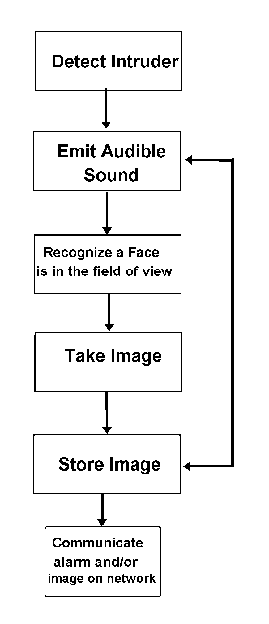
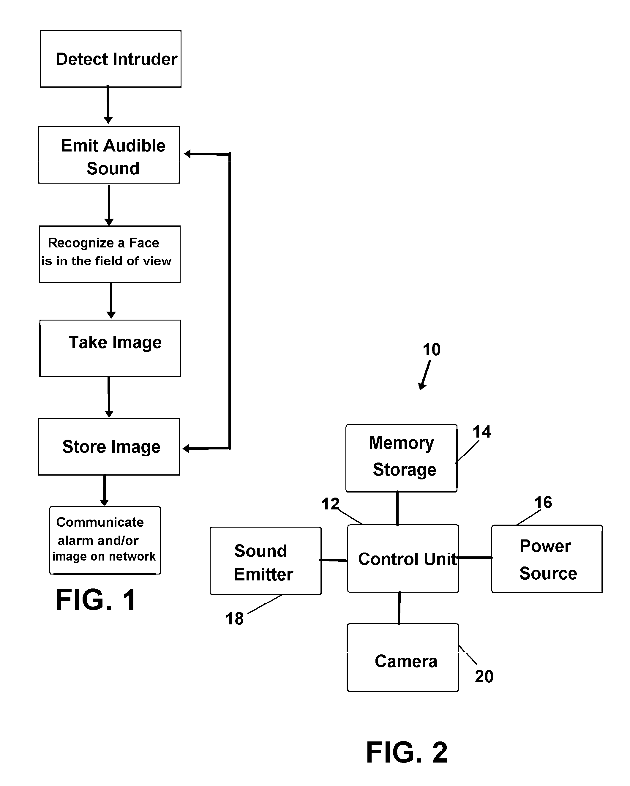
[0055]Now referring to drawings in FIGS. 1-7, wherein similar components are identified by like reference numerals, there is seen in FIG. 1 a preferred flow chart of the intruder identification system 10. In general, the invention provides a means to capture identifiable facial images of intruders by detecting the presence of the intruder, emitting an audible sound to cause the intruder to gaze in the line of sight of video capturing means, employing facial recognition software to capturing the facial image, and storing or sending the captured data to a remote location. It is noted that this invention...


PUM


Abstract

An intruder identification system for capturing a digital image in a field of view generally comprising an image capturing device and one or a plurality of sound emitters for attracting a gaze of an intruder and a turning of their face to an image capturing position in the field of view. A preferred image capturing position being when both eyes of the intruder are viewable in the field of view of the image capturing device, detectable by the employment of facial recognition software adapted at the task and thereafter digitally storing the image. The identity of the intruder may be determined using software adapted to identify individuals from the captured facial image. The system may also employ means for electronic communication for transmitting the digital image to a video display operatively connected with a users receiving device, such as a smart phone.

Description

[0001]This application claims priority to U.S. Provisional Application, 61 / 573,224, which was filed on Sep. 2, 2011, and which is incorporated herein in its entirety by reference.BACKGROUND OF THE INVENTION[0002]1. Field of the Invention[0003]The present invention relates to intruder identification systems and methods. More particularly the invention relates to an intruder identification system and method comprising a surveillance camera and means to attract the gaze of an intruder at or towards the camera in order to capture an identifiable facial image.[0004]2. Prior Art[0005]Video and audio surveillance is employed by business and individuals alike in order to protect themselves and their property, as well as provide peace of mind and safety for loved ones. A conventional surveillance method is to employ video capturing devices at entryways or other highly trafficked areas in order to capture video surveillance of intruders. These devices often include recording means which save ...

Claims


Application Information

Patent Timeline
IPC IPC(8): G06K9/62H04N7/18
CPCG06K9/00771G06K9/00255G06V40/166G06V20/52
Inventor BARANEK, JOHN
Owner BARANEK JOHN
Learn More