Method and apparatus for robust packet distribution among hierarchical managed switching elements

a hierarchical managed switching and packet distribution technology, applied in data switching networks, frequency-division multiplexes, instruments, etc., can solve problems such as the inability of managed edge switching elements to process packets

Active Publication Date: 2013-03-07
NICIRA
View PDF18 Cites 180 Cited by
  • Summary
  • Abstract
  • Description
  • Claims
  • Application Information

AI Technical Summary

Benefits of technology

[0003]To distribute the processing of packets across the managed non-edge switching elements, some embodiments determine a managed non-edge switching element based on a hash function. In some embodiments, the method applies the hash function on the packet's header (e.g., source media access control (MAC) address, destination MAC address, etc.) to g

Problems solved by technology

The managed edge switching element may not be a

Method used


Image

  • Method and apparatus for robust packet distribution among hierarchical managed switching elements
  • Method and apparatus for robust packet distribution among hierarchical managed switching elements
  • Method and apparatus for robust packet distribution among hierarchical managed switching elements

Examples


Embodiment Construction

[0054]In the following detailed description of the invention, numerous details, examples, and embodiments of the invention are set forth and described. However, it will be clear and apparent to one skilled in the art that the invention is not limited to the embodiments set forth and that the invention may be practiced without some of the specific details and examples discussed.

I. Environment

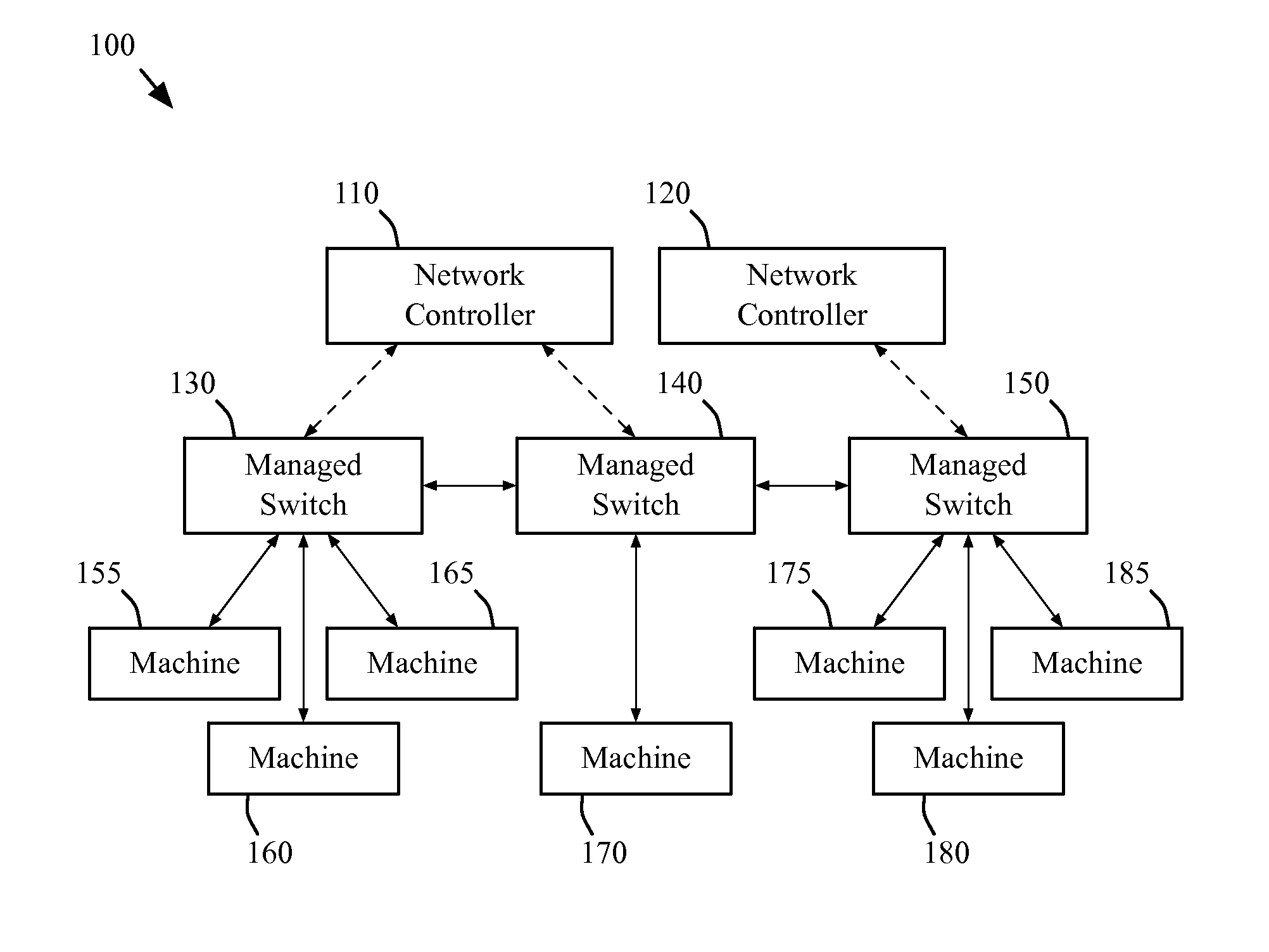
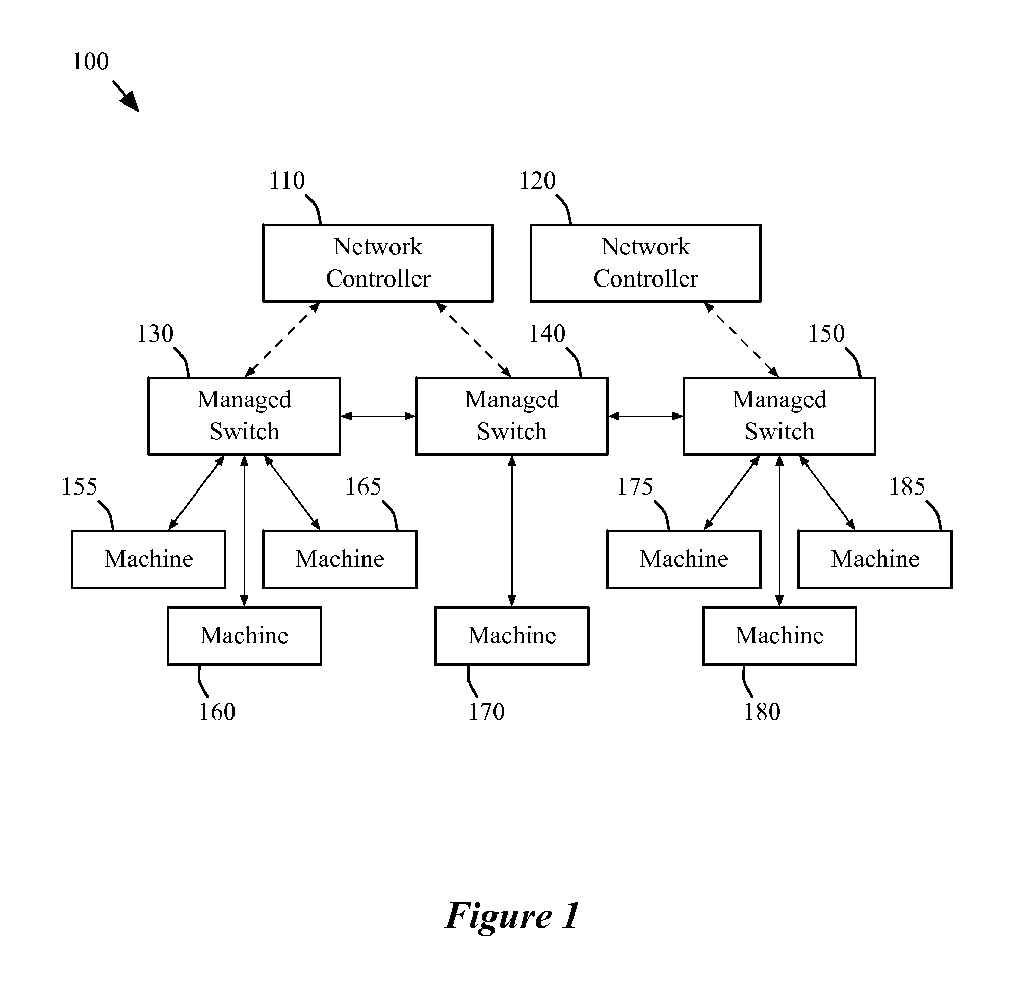
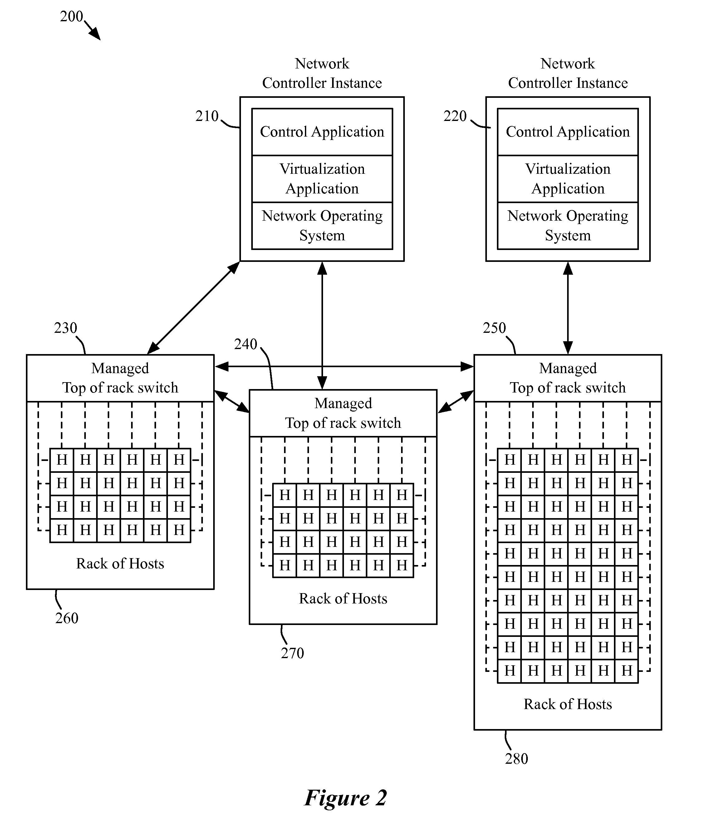
[0055]The following section will describe the environment in which some embodiments of the inventions are implements. In the present application, switching elements and machines may be referred to as network elements. In addition, a network that is managed by one or more network controllers may be referred to as a managed network in the present application. In some embodiments, the managed network includes only managed switching elements (e.g., switching elements that are controlled by one or more network controllers) while, in other embodiments, the managed network includes managed switching ele...


PUM


Abstract

For a network that includes several managed edge switching elements and several managed non-edge switching elements that are for implementing a logical switching element, some embodiments provide a method of distributing packet processing across the several managed non-edge switching elements. The method receives a packet for processing through the logical switching element. Based on a determination that the packet needs to be processed by a managed non-edge switching element, the method determines a particular managed non-edge switching element of the several managed non-edge switching elements to forward the packet. The method forwards the packet to the particular managed non-edge switching element for the particular managed non-edge switching element to process the packet.

Description

CLAIM OF BENEFIT TO PRIOR APPLICATION[0001]This application is a continuation in part application of U.S. patent application Ser. No. 13 / 177,535, filed on Jul. 6, 2011. U.S. patent application Ser. No. 13 / 177,535 claims benefit to U.S. Provisional Patent Application 61 / 361,912, filed on Jul. 6, 2010; U.S. Provisional Patent Application 61 / 361,913, filed on Jul. 6, 2010; U.S. Provisional Patent Application 61 / 429,753, filed on Jan. 4, 2011; U.S. Provisional Patent Application 61 / 429,754, filed on Jan. 4, 2011; U.S. Provisional Patent Application 61 / 466,453, filed on Mar. 22, 2011; U.S. Provisional Patent Application 61 / 482,205, filed on May 3, 2011; U.S. Provisional Patent Application 61 / 482,615, filed on May 4, 2011; U.S. Provisional Patent Application 61 / 482,616, filed on May 4, 2011; U.S. Provisional Patent Application 61 / 501,743, filed on Jun. 27, 2011; and U.S. Provisional Patent Application 61 / 501,785, filed on Jun. 28, 2011. These applications, namely 13 / 177,535, 61 / 361,912, 6...

Claims


Application Information

Patent Timeline
IPC IPC(8): H04L12/26H04L45/74
CPCH04L45/745
Inventor CASADO, MARTINKOPONEN, TEEMUTHAKKAR, PANKAJLAMBETH, W. ANDREWYIP, ALEXANDERAMIDON, KEITH E.INGRAM, PAUL S.
Owner NICIRA
Why Eureka
Try Eureka