Radio station, transmitting station, and frequency band sharing method

a technology of radio station and frequency band, applied in the field of radio station, transmitting station, and frequency band sharing method, can solve the problems of deteriorating signal quality in the priority system, affecting and reducing the transmission opportunity of signals from non-priority systems. , to achieve the effect of preventing the deterioration of signal quality and increasing the transmission opportunity of signals

Active Publication Date: 2013-03-07
NTT DOCOMO INC
View PDF4 Cites 1 Cited by
  • Summary
  • Abstract
  • Description
  • Claims
  • Application Information

AI Technical Summary

Benefits of technology

[0007]The present invention was made in view of such a respect, and it is an object of the invention to provide a radio station, a transmitting station and a frequency band sharing method for increasing transmission opportunities of signals in a non-priority system, while preventing signal quality from deteriorating in a priority system, when frequencies are shared among a plurality of radio communication systems including the priority system and non-priority system.
[0009]According to this configuration, the broadcast section broadcasts the load information of the first radio communication system to the transmitting station in the second radio communication system, and it is thereby possible to increase the transmission opportunity of the second radio communication system signal transmitted from the transmitting station in the second radio communication system. Further, by increasing the allowable interference level of the first radio communication system signal based on the predicted interference power acquired in the acquisition section, it is possible to prevent the quality of the first radio communication system signal received in the receiving station in the first radio communication system from deteriorating due to the second radio communication system signal transmitted using the shared frequency band.
[0010]Further, in the radio station, the allowable interference level control section increases transmission power of the first radio communication system signal or decreases a transmission rate of the first radio communication system signal based on the predicted interference power acquired in the acquisition section.
[0013]Moreover, the radio station further can have an adjacent cell interference control section (adjacent cell interference control section 107) that decreases interference power caused in the receiving station in the first radio communication system by an adjacent cell based on the predicted interference power acquired in the acquisition section.
[0015]According to this configuration, by determining whether transmission of the second radio communication system signal using the shared frequency band is possible or not based on the load information of the first radio communication system acquired in the acquisition section, it is possible to increase the transmission opportunity of the second radio communication system signal transmitted from the transmitting station in the second radio communication system. Further, the broadcast section broadcasts the predicted interference power to the receiving station or transmitting station in the first radio communication system, and it is thereby possible to prevent the quality of the first radio communication system signal received in the receiving station in the first radio communication system from deteriorating due to the second radio communication system signal transmitted using the shared frequency band.
[0020]It is possible to provide a radio station, transmitting station and frequency band sharing method for increasing transmission opportunities of signals in a non-priority system, while preventing signal quality from deteriorating in a priority system, when frequencies are shared among a plurality of radio communication systems including the priority system and non-priority system.

Problems solved by technology

However, in the above-mentioned conventional technique, even when the load of the priority system is allowable, the non-priority system does not transmit a signal in the case where a signal from the priority system exits.
Therefore, a problem arises that although the load of the priority system is allowable, a transmission opportunity of a signal from the non-priority system is restricted.
However, in this case, when a receiver in the priority system is located near a transmitter in the non-priority system, an interference level in the receiver in the priority system rapidly increases by a transmission signal from the non-priority system.
Therefore, there is a problem that signal quality deteriorates in the priority system.

Method used


Image

  • Radio station, transmitting station, and frequency band sharing method
  • Radio station, transmitting station, and frequency band sharing method
  • Radio station, transmitting station, and frequency band sharing method

Examples


embodiment 1

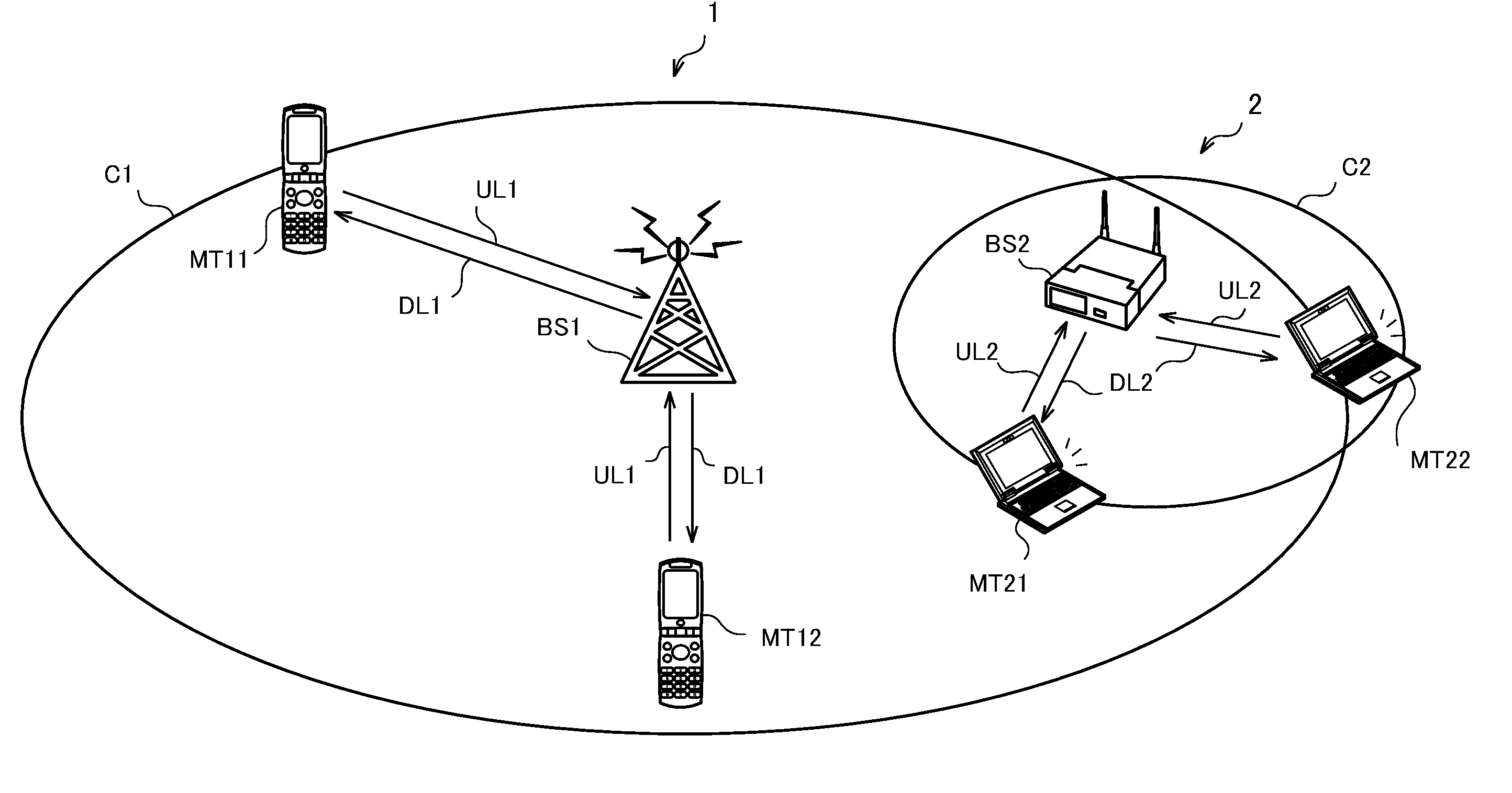
[0041]FIG. 1 is a schematic diagram of a radio communication system according to Embodiment 1 of the invention. As shown in FIG. 1, a radio communication system 1 and radio communication system 2 are operated in the same or adjacent areas.

[0042]Further, the radio communication system 1 and radio communication system 2 share the same or adjacent frequency bands. In use of the shared frequency band, the radio communication system 1 has a priority over the radio communication system 2. In other words, the radio communication system 1 is a priority system, and the radio communication system 2 is a non-priority system.

[0043]The radio communication system 1 is comprised of a base station BS1 and mobile stations MT11 and MT12. The base station BS1 receives uplink signals UL1 from the mobile stations MT11 and MT12 existing in a cell C1, while transmitting downlink signals DL1 to the mobile stations MT11 and MT12. The radio communication system 1 is a mobile communication system, for example...

modification 1-1

(Modification 1-1)

[0070]Modification 1-1 in Embodiment 1 describes the case where a shared frequency band is shared between the uplink signal UL1 in the radio communication system 1 and the uplink signal UL2 in the radio communication system 2.

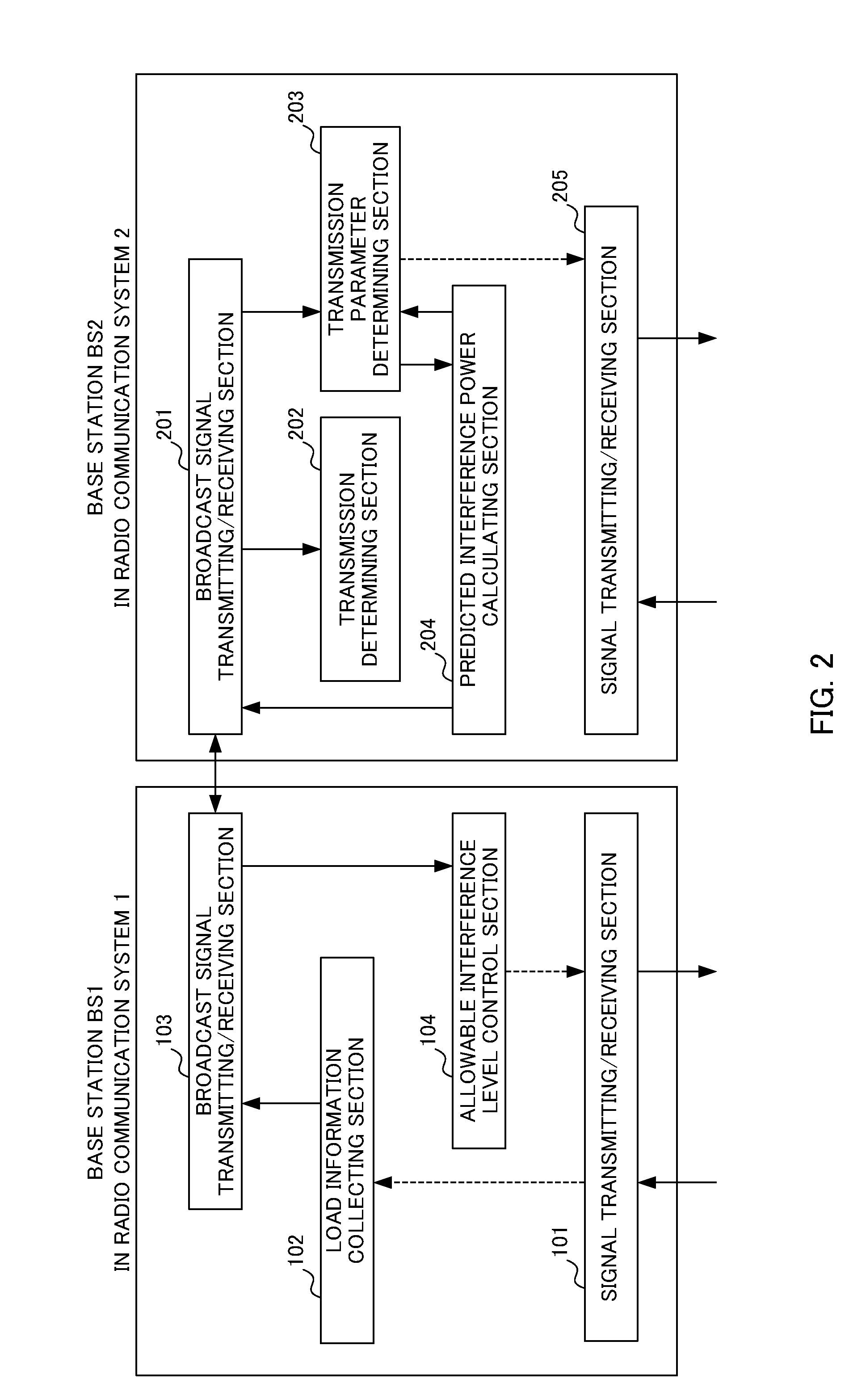
[0071]Referring to FIG. 6, the frequency band sharing processing according to Modification 1-1 will be described, while focusing on the difference from the frequency band sharing processing in above-mentioned Embodiment 1. In Modification 1-1, the mobile station MT2 is provided with the configuration of the base station BS2 as shown in FIG. 2, and the above-mentioned frequency band sharing processing is performed between the base station BS1 (receiving station) in the radio communication system 1 and the mobile station MT2 (transmitting station) in the radio communication system 2.

[0072]More specifically, as shown in FIG. 6, the mobile station MT2 in the radio communication system 2 receives a broadcast signal transmitted from the base station...

modification 1-2

(Modification 1-2)

[0076]Modification 1-2 in Embodiment 1 describes the case where a shared frequency band is shared between the downlink signal DL1 in the radio communication system 1 and the downlink signal DL2 in the radio communication system 2.

[0077]Referring to FIG. 7, the frequency band sharing processing according to Modification 1-2 will be described, while focusing on the difference from the frequency band sharing processing in above-mentioned Embodiment 1. In Modification 1-2, the above-mentioned frequency band sharing processing is performed between the base station BS1 (transmitting station) in the radio communication system 1 and the base station BS2 (transmitting station) in the radio communication system 2.

[0078]More specifically, as shown in FIG. 7, the base station BS1 in the radio communication system 1 collects reception quality information of the downlink signal DL1 from each mobile station MT1. The base station BS1 transmits to the base station BS2 a broadcast s...


PUM


Abstract

The invention has a step where a transmitting station in a second radio communication system determines whether transmission of a second radio communication system signal using a shared frequency band is possible or not based on load information of a first radio communication system broadcast from a base station in the first radio communication system, a step where the transmitting station in the second radio communication system calculates predicted interference power caused in a receiving station in the first radio communication system by the second radio communication system signal transmitted using the shared frequency band, and a step where the base station in the first radio communication system increases an allowable interference level of a first radio communication system signal transmitted using the shared frequency band based on the predicted interference power broadcast from the transmitting station in the second radio communication system.

Description

CROSS REFERENCE TO RELATED APPLICATIONS[0001]This application is a continuation of U.S. application Ser. No. 12 / 832,139, filed Jul. 8, 2010, now pending, which is based upon and claims the benefit of priority from the prior Japanese Patent Application No. 2009-164244, filed on Jul. 10, 2009; each of which are incorporated herein by reference in their entireties.FIELD OF THE INVENTION[0002]The present invention relates to a radio station in a first radio communication system using a shared frequency band which the first radio communication system uses in priority to a second radio communication system, a transmitting station in the second radio communication system, and a method of sharing the frequency band.BACKGROUND[0003]Conventionally, as a technique of sharing frequencies among a plurality of radio communication systems including a priority system and a non-priority system, such a technique is known that the non-priority system transmits a signal using a shared frequency band in...

Claims


Application Information

Patent Timeline
Patent Type & Authority Applications(United States)
IPC IPC(8): H04B15/00H04W72/04
CPCH04W16/14H04W88/08H04W52/243
Inventor HARADA, HOROKIFUJII, HIROMASAASAI, TAKAHIROOHYA, TOMOYUKI
Owner NTT DOCOMO INC
Why Eureka
Try Eureka