Proximal humerus greater tuberosity hook-arm clip

a greater tuberosity and humerus technology, applied in the field of bone fracture fixation, can solve the problems of significantly affecting the quality of life of patients, inability to use, and difficulty in fixing with currently available bone plate and suturing methods, and achieve the effect of stabilizing the fractured greater tuberosity

Inactive Publication Date: 2013-03-07
UNIV OF MARYLAND BALTIMORE
View PDF2 Cites 11 Cited by
  • Summary
  • Abstract
  • Description
  • Claims
  • Application Information

AI Technical Summary

Benefits of technology

[0010]In one aspect, the invention provides a bone plate for stabilizing a fractured greater tuberosity of the proximal humerus, wherein the bone plate comprises one or more apertures for fixing the bone plate to the humerus bone; one or more hook-arm receivers in the bone plate; and one or more attachable hook-arms comprising one or more prongs and a device for attachment to the bone plate.
[0014]In another aspect, the invention provides a method for stabilizing a fractured greater tuberosity in a subject comprising: i) attaching the bone plate of the invention to the humerus of a subject having a fractured greater tuberosity; ii) making one or more holes into the greater tuberosity; iii) securing the one or more prongs from the hook-arm into the holes of ii); iv) inserting the hook-arm attachment device into the hook-arm receiver; and v) securing the hook-arm to the bone plate, thereby stabilizing the fractured greater tuberosity.

Problems solved by technology

Fractures of the greater tuberosity present a unique problem because they often occur on the side of the humeral head making them difficult to fixate with currently available bone plate and suturing methods.
As such, failure to properly repair a greater tuberosity fracture can significantly impact a patient's quality of life.
Although internal fixation with bone plates and screws has been achieved, often times they cannot be used because the smaller fragments of the fracture site would not be able to withstand forces exerted by the screws.
However, the hooks on these plates are rigidly attached to the end of an elongated body and therefore could not be used to fixate a fractured greater tuberosity.
However, there are shortcomings with a suturing approach to reduce a fractured greater tuberosity because sutures may not provide adequate function for larger bone fragments.
The currently available devices and methods for securing a fractured greater tuberosity present undesirable limitations and there is a need for improved devices and methods to secure a fractured greater tuberosity.

Method used


Image

  • Proximal humerus greater tuberosity hook-arm clip
  • Proximal humerus greater tuberosity hook-arm clip
  • Proximal humerus greater tuberosity hook-arm clip

Examples


Embodiment Construction

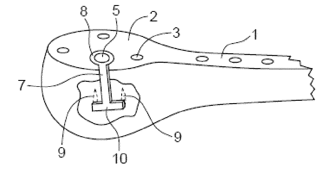
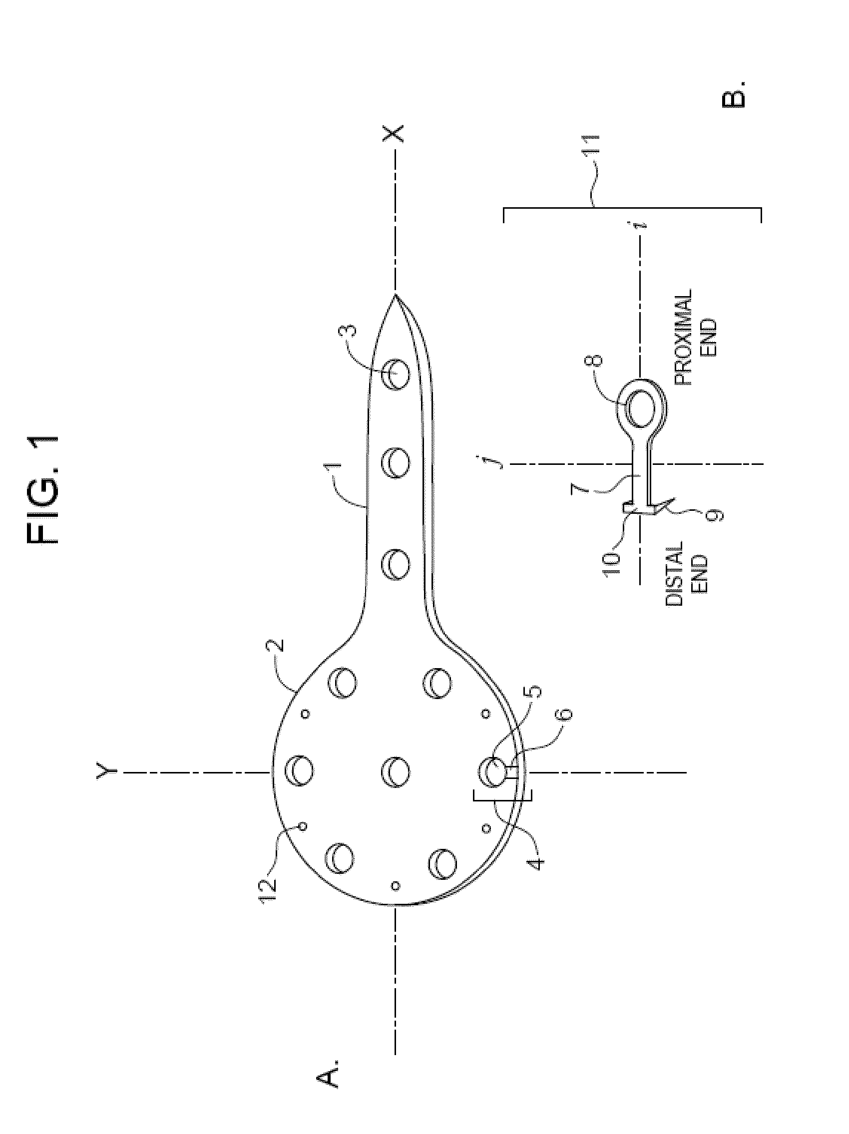
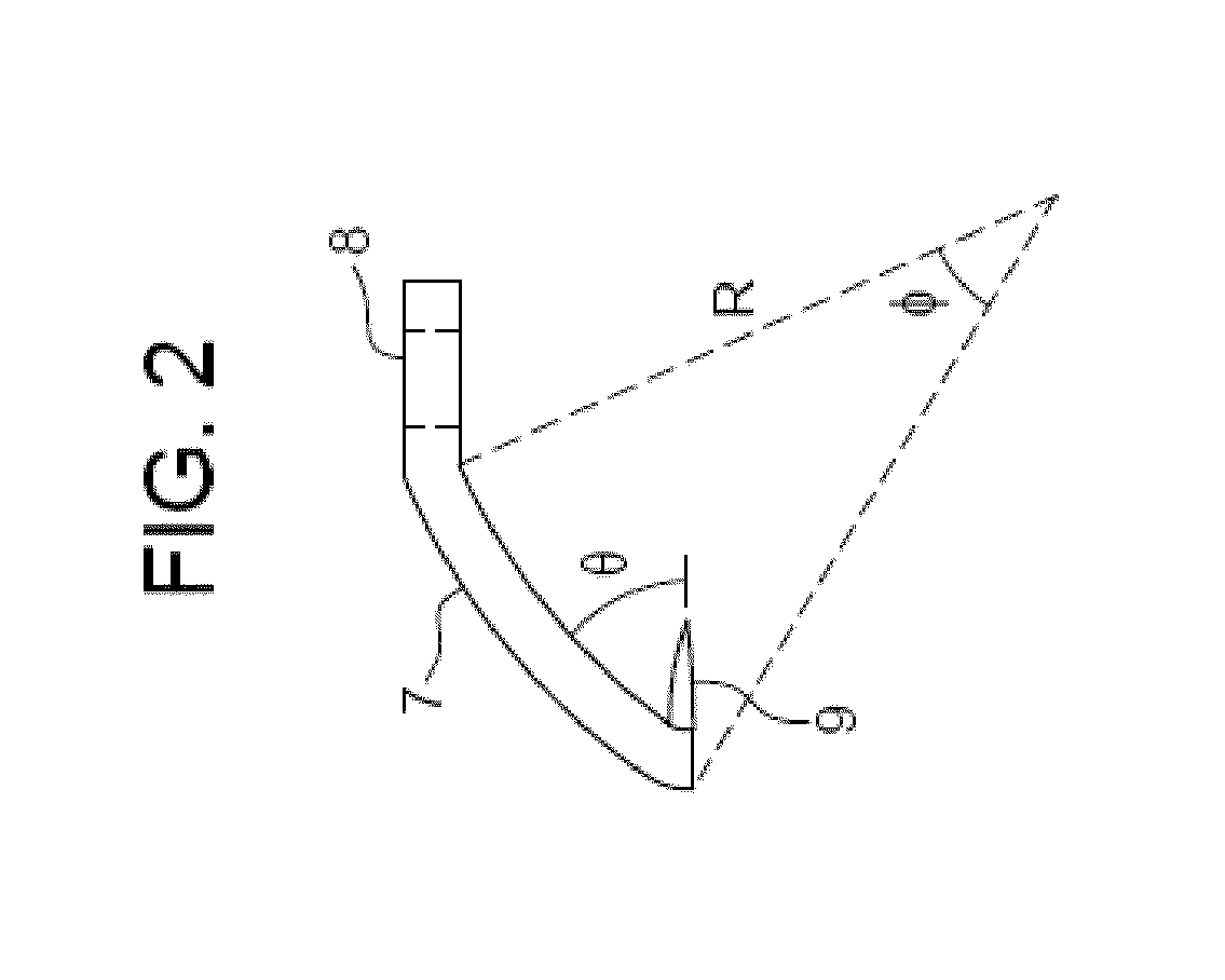
[0023]The invention is based on the discovery that a fractured greater tuberosity of the proximal humerus can be secured with a bone plate with an attached hook-arm.

[0024]For the purposes of promoting an understanding of the principles of the invention, reference will now be made to certain embodiments and specific language will be used to describe the same. It will nevertheless be understood that no limitation of the scope of the invention is thereby intended, and alterations and modifications in the illustrated device, and further applications of the principles of the invention as illustrated therein are herein contemplated as would normally occur to one skilled in the art to which the invention relates.

[0025]Unless defined otherwise, all technical and scientific terms used herein have the same meaning as commonly understood by one of ordinary skill in the art to which this invention pertains.

[0026]For the purpose of interpreting this specification, the following definitions will ...


PUM


Abstract

The invention relates to a bone plate for stabilizing a fractured greater tuberosity, wherein the bone plate comprises one or more apertures for fixing the bone plate to bone; one or more hook-arm receivers; one or more attachable hook-arms comprising one or more prongs and a device for attachment to the bone plate. The invention also relates to methods for stabilizing a fractured greater tuberosity using the bone plates of the invention and kits comprising the same.

Description

CROSS REFERENCE TO RELATED APPLICATIONS[0001]This application claims the benefit of U.S. Appl. No. 61 / 529,631, filed Aug. 31, 2011. The content of the aforesaid application is relied upon and incorporated by reference in its entirety.BACKGROUND OF THE INVENTION[0002]1. Field of the Invention[0003]The field of the invention relates generally to bone fracture fixation and, more particularly, to the fixation of bone fractures of the greater tuberosity.[0004]2. Description of the Related Art[0005]Fractures of the greater tuberosity present a unique problem because they often occur on the side of the humeral head making them difficult to fixate with currently available bone plate and suturing methods. In spite of the difficulty, it is very important to properly repair a greater tuberosity fracture. A superiorly displaced tuberosity can block abduction of the shoulder, whereas a posteriorly displaced tuberosity may impinge against the posterior glenoid and block external rotation. As such...

Claims


Application Information

Patent Timeline
Patent Type & Authority Applications(United States)
IPC IPC(8): A61B17/80A61B17/88
CPCA61B17/80
Inventor EGLSEDER, JR., WALTER ANDREW
Owner UNIV OF MARYLAND BALTIMORE
Why Eureka
Try Eureka