Control device and control method for electric vehicle

Active Publication Date: 2013-03-07
HONDA MOTOR CO LTD
View PDF30 Cites 33 Cited by
  • Summary
  • Abstract
  • Description
  • Claims
  • Application Information

AI Technical Summary

Benefits of technology

The patent text describes a technique that allows a vehicle to maintain its stopped state for a predetermined period of time after braking is released. This is done by limiting the time for the motor to generate torque to keep the vehicle in place. After the predetermined time has passed, the brake driving device is activated to keep the vehicle in its stopped state. This technique helps to reduce the amount of electricity used while maintaining the vehicle's position.

Problems solved by technology

Thereby, it is liable for the switching element to become overheated.

Method used


Image

  • Control device and control method for electric vehicle
  • Control device and control method for electric vehicle
  • Control device and control method for electric vehicle

Examples


Embodiment Construction

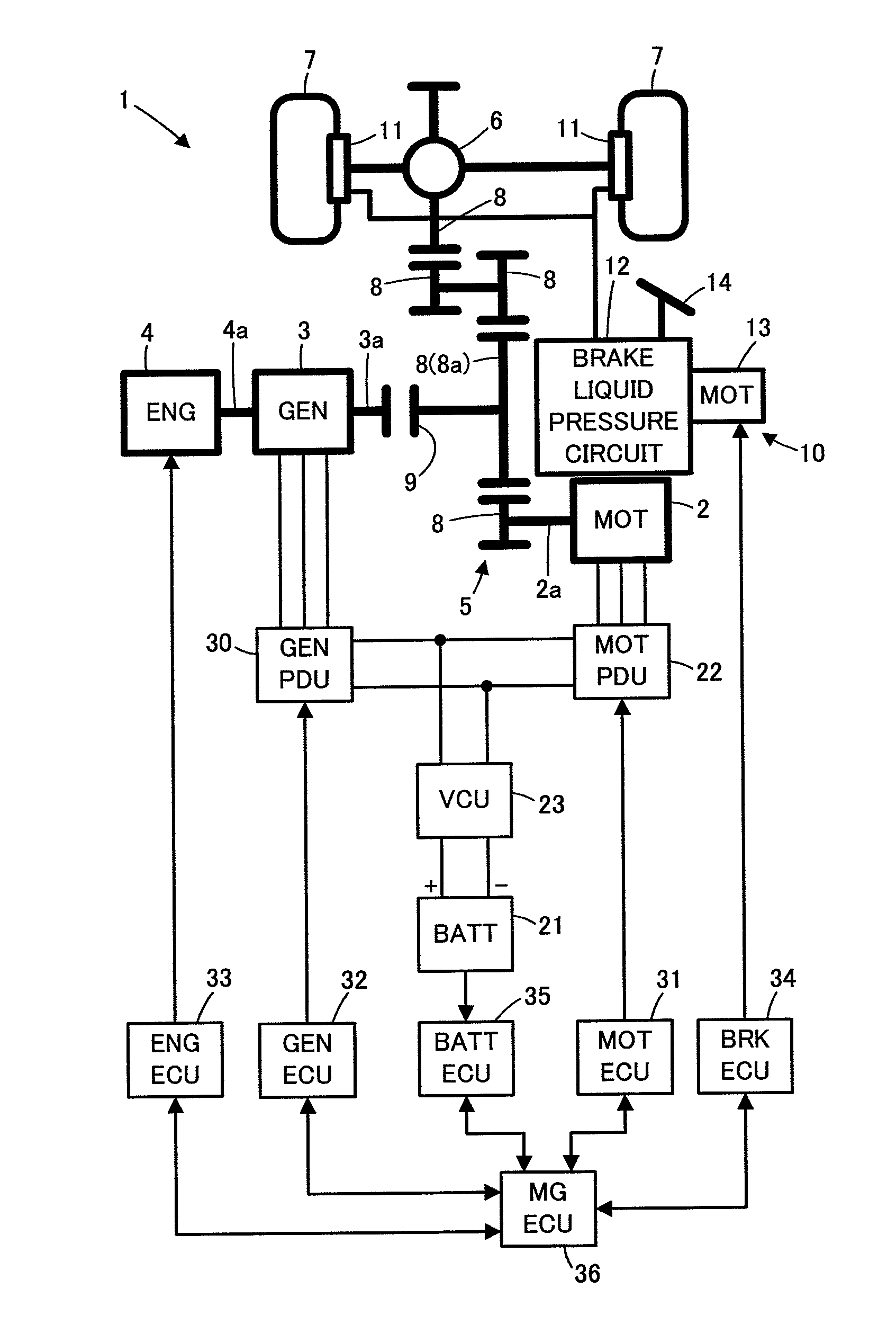
[0029]An embodiment of the present invention will be described with reference to FIG. 1 to FIG. 9.

[0030]Firstly, the mechanical configuration of an electric vehicle of the present embodiment will be described. With reference to FIG. 1, the electric vehicle of the present embodiment (may be simply referred to as the vehicle 1 hereinafter) is provided with an electric motor 2 serving as a generation source of a driving force of the vehicle 1, a generator 3 and an engine 4 for driving the generator 3. In the present embodiment, the engine 4 may be used as the generation source of a driving force of the vehicle 1. Therefore, the electric vehicle 1 of the present embodiment may operate as a series hybrid vehicle or a parallel hybrid vehicle.

[0031]The electric motor 2 is disposed with a rotary shaft 2a rotating integrally with a rotor (not drawn). The rotary shaft 2a is connected to a pair of wheels (driving wheels) 7, 7 through the intermediary of a power transmission mechanism 5 and a d...


PUM


Abstract

If the temperature (Tig) of a switching element (25) in a source power supply circuit (24) of an electric motor (2) increases to be equal to or greater than a first predetermined value (α) while an electric vehicle (1) is in a stall state, a torque command for the electric motor (2) is reduced while a braking force command for a brake unit (10) is increased, and if the temperature (Tig) of the switching element (25) subsequently decreases to be equal to or less than a second predetermined value (β(<α)), the braking force command for the brake unit (10) is decreased while the torque command for the electric motor (2) is increased. The increment rate of the torque command for the electric motor (2) is varied in accordance with the degree of road gradient.

Description

TECHNICAL FIELD[0001]The present invention relates to a control device and a control method for an electric vehicle provided with an electric motor which serves as a generation source of a driving force of the vehicle.BACKGROUND ART[0002]In an electric vehicle provided with an electric motor such as a synchronous motor or the like serving as a generation source of a driving force of the vehicle, a driving torque output from the electric motor is transmitted to driving wheels of the vehicle via a power transmission mechanism such as a transmission or the like to generate the driving force for the vehicle.[0003]When the electric vehicle of this type is on an ascending slope or the like, it is possible that an operation state of the vehicle is in a so-called stall state. The stall state refers to such a state that even though the driving torque generated in the electric motor according to manipulations of an accelerator or the like of the vehicle is being transmitted to the driving whe...

Claims


Application Information

Patent Timeline
IPC IPC(8): B60W20/00B60W10/192B60W10/08
CPCB60K6/442Y02T10/7275B60L2240/525B60T13/745B60W10/08B60W10/184B60W20/00B60W30/18109B60W2510/087Y02T10/6234B60T17/221B60L2240/423B60L15/2081Y02T10/642B60L7/18Y02T10/62Y02T10/64Y02T10/72B60W10/188
Inventor MATSUSHITA, MASANORIFUJISHIRO, NAOKISAITO, OSAMUKOBORI, HIDETOSHIMATSUSHITA, SATOSHI
Owner HONDA MOTOR CO LTD
Why Eureka
Try Eureka