Visibility Control Device for a Vehicle

Active Publication Date: 2020-03-05
TOYOTA JIDOSHA KK
View PDF0 Cites 4 Cited by
  • Summary
  • Abstract
  • Description
  • Claims
  • Application Information

AI Technical Summary

Benefits of technology

The present invention provides a visibility control device for a vehicle that can reduce any discomfort or fatigue experienced by a vehicle occupant when traveling at high speeds. This is achieved by controlling a light-shielding portion that prevents the angle of depression between the line of sight of the occupant and the road surface when the vehicle speed is equal to or greater than a predetermined value. The light-shielding portion can have at least two or more light-shielding states that adjust the surface area of the light-shielded areas based on the speed of the vehicle. Additionally, the light-shielding state can be maintained for a predetermined time to prevent excessive switching between the light-shielding state and the light-transmitting state. Overall, the visibility control device can provide a safer and more comfortable driving experience for the vehicle occupant.

Problems solved by technology

As a result, there is a possibility that this might lead to the vehicle occupant experiencing a sense of discomfort, and may also cause the vehicle occupant to become fatigued.

Method used


Image

  • Visibility Control Device for a Vehicle
  • Visibility Control Device for a Vehicle
  • Visibility Control Device for a Vehicle

Examples


first exemplary embodiment

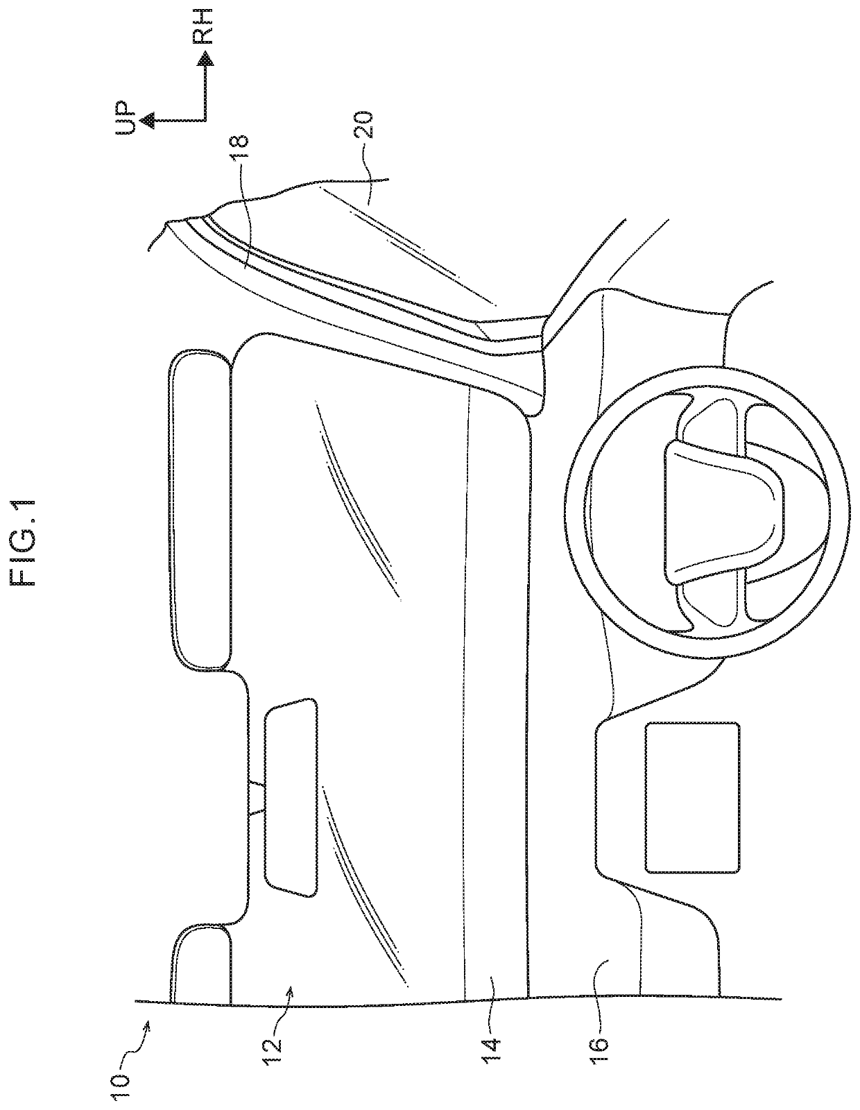
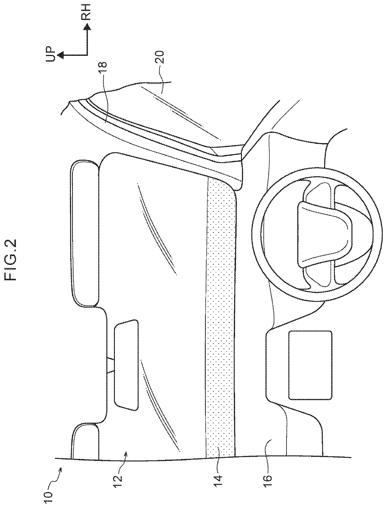
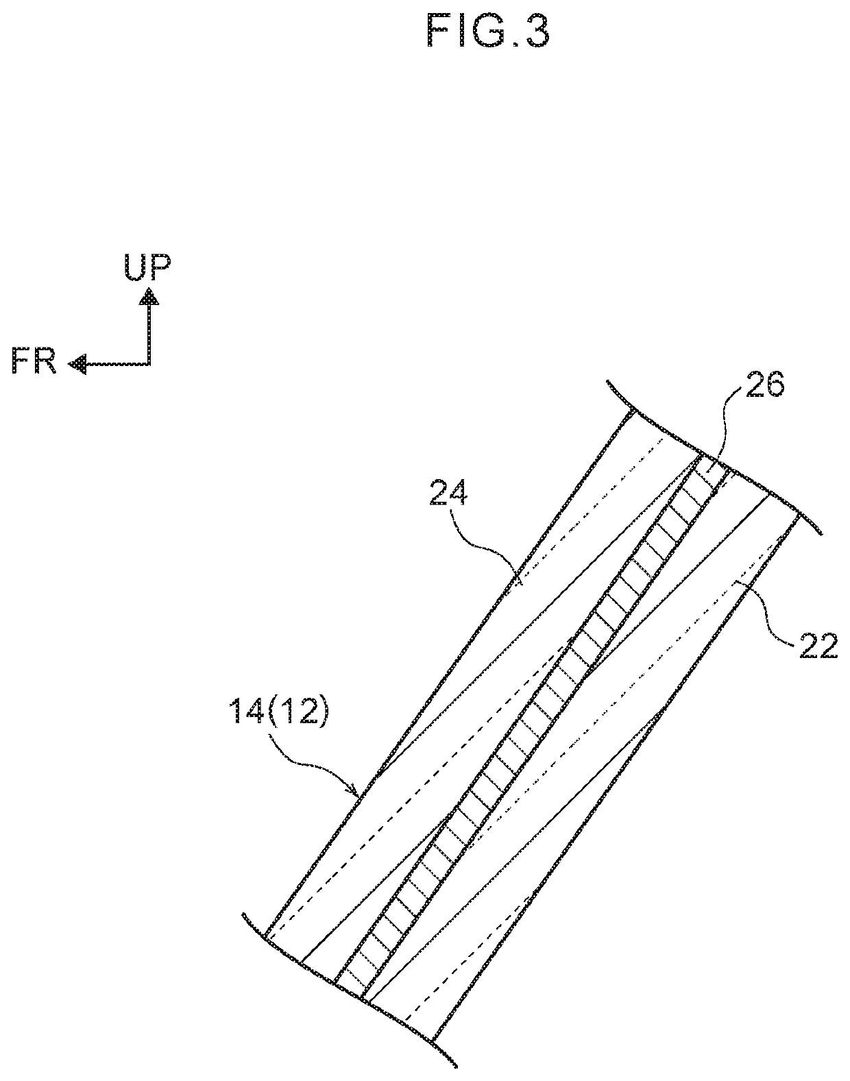
[0031]Next, a visibility control device for a vehicle according to the exemplary embodiments will now be described using FIG. 1 through FIG. 10. Note that an arrow FR, an arrow RH, and an arrow UP that are illustrated in the appropriate drawings respectively indicate a front side in a vehicle front-rear direction, a right side in a vehicle width direction, and an upper side in a vehicle up-down direction. Hereinafter, if simple front-rear or up-down directions are used in the following description, then, unless specifically stated otherwise, these refer respectively to the front-rear directions of the vehicle and the up-down directions of the vehicle. Additionally, the following description and drawings may be simplified where this is appropriate in order to clarify the description.

[0032]As illustrated in FIG. 1, a windshield 12 is provided in a front end portion of a vehicle cabin of a vehicle 10 in which a visibility control device for a vehicle according to the present exemplary ...

second exemplary embodiment

[0071]Next, a visibility control device for a vehicle according to a second exemplary embodiment will be described with reference to FIG. 7 and FIG. 8. Note that structure of the second exemplary embodiment that is similar to that of the first exemplary embodiment is given the same descriptive symbol, and any description thereof is omitted where appropriate.

[0072]The present exemplary embodiment differs from the first exemplary embodiment in that the light-shielding portion 14 has plural light-shielding states (S1 through S4).

[0073]As is illustrated in FIG. 7A, in the visibility control device for a vehicle according to the present exemplary embodiment, the light-shielding portion 14 has plural light-shielded areas from S1 through to S4. These respective light-shielded areas have mutually different surface areas, and the surface area of the light-shielded areas increases towards the vehicle upper side progressively in sequence from the light-shielded area S1 through to the light-shi...

third exemplary embodiment

[0102]Next, a visibility control device for a vehicle according to a third exemplary embodiment will be described with reference to FIG. 9 and FIG. 10.

[0103]The present exemplary embodiment differs from the first and second exemplary embodiments in that the light-shielding portion 14 is replaced by a head-up display device 40 (hereinafter, referred to as a HUD 40).

[0104]In FIG. 9, the HUD 40 is provided on the vehicle front side of a driver's seat. The HUD 40 displays basic vehicle information such as the traveling speed of the vehicle 10 and the like by linking with various instruments such as, for example, meters and the like (not illustrated in the drawings).

[0105]The HUD 40 is incorporated into the instrument panel 16 of the vehicle, and is provided with a light source portion 40A that is formed by light sources such as, for example, LED and the like, and with a transparent display portion 40B that is provided in front of the instrument panel 16, and that projects light emitted ...


PUM

PropertyMeasurementUnit
Timeaaaaaaaaaa
Surface areaaaaaaaaaaa
Lightaaaaaaaaaa

Abstract

A visibility control device for a vehicle includes: a windshield that is provided at a front side of a vehicle cabin; a light-shielding portion that is provided at, or so as to correspond to, an area at a vehicle lower side of the windshield, and that is switchable between a light-shielding state and a light-transmitting state; a vehicle speed sensor that detects a speed of a vehicle; and a control unit that, in a case in which a vehicle speed detected by the vehicle speed sensor is equal to or greater than a predetermined value, performs control to switch the light-shielding portion to the light-shielding state, and in a case in which the vehicle speed is less than a predetermined value, performs control to switch the light-shielding portion to the light-transmitting state.

Description

CROSS-REFERENCE TO RELATED APPLICATION[0001]This application is based on and claims priority under 35 USC 119 from Japanese Patent Application No. 2018-160772 filed on Aug. 29, 2018, the disclosure of which is incorporated by reference herein.BACKGROUNDTechnical Field[0002]The present disclosure relates to a visibility control device for a vehicle.Related Art[0003]Japanese Patent Application Laid-Open (JP-A) No. 2007-308069 discloses an anti-glare device for a vehicle that enables the glare on a vehicle occupant to be reduced by controlling a light-shielded area using a shield portion that is disposed in an upper portion of a front windshield glass in accordance with detection results from an illuminometer provided in the vehicle.[0004]In this anti-glare device for a vehicle, although the light-shielded area in the upper portion of the front windshield is controlled, when the vehicle is traveling at high speed, from the viewpoint of a vehicle occupant, the road surface in front of t...

Claims


Application Information

Patent Timeline
IPC IPC(8): B32B17/10B60J3/04G02F1/1335G02F1/1337
CPCB32B17/10504B60Y2400/303G02F1/133512G02F1/1337B60J3/04
Inventor SAKURAI, HIDEYUKI
Owner TOYOTA JIDOSHA KK
Why Eureka
Try Eureka