Magnetic encoder

a technology of magnetic encoder and encoder, which is applied in the direction of measuring devices, instruments, and using electrical means, etc., can solve the problems of reducing detection sensitivity, increasing production cost, and increasing undesirable effects of magnetic interference, so as to reduce detection sensitivity, increase magnetic interference, and prevent possible failures.

Active Publication Date: 2013-03-14
NTN CORP
View PDF19 Cites 76 Cited by
  • Summary
  • Abstract
  • Description
  • Claims
  • Application Information

AI Technical Summary

Benefits of technology

[0014]A plural-row magnetic encoder is often used to provide a rotation sensor or an angle sensor for control of a rotational device. In this case, reduction of the space between the plural magnetic tracks may lead to increase in magnetic interference between the magnetic tracks, thereby resulting in reduced detection sensitivity. Such undesirable effects of magnetic interference may be greater when the plural rows of magnetic tracks are brought closer as well as when magnetic sensors are positioned at locations closer to a boundary line defined between the plural rows of magnetic tracks. Also, for successful incorporation of the sensors into a device, a sufficient air gap may be required between a magnetic encoder—which is a rotational member—and sensors—which are stationary members, to safely prevent possible failures that may be caused by, for example, an accidental contact.
[0015]A separator made of a magnetic material may be interposed between the plural rows of magnetic tracks to reduce such magnetic interference. However, this may complicate the construction of a magnetic encoder, leading to increase in the production cost. Also, a magnetic material may short-circuit part of magnetic field emanating from a magnetic encoder, thereby leading to reduced magnetic force at sensors. Increased distance between the magnetic tracks may reduce magnetic interference, but this may require a larger mounting space, preventing reduction in the size of a detection device.

Problems solved by technology

In this case, reduction of the space between the plural magnetic tracks may lead to increase in magnetic interference between the magnetic tracks, thereby resulting in reduced detection sensitivity.
Such undesirable effects of magnetic interference may be greater when the plural rows of magnetic tracks are brought closer as well as when magnetic sensors are positioned at locations closer to a boundary line defined between the plural rows of magnetic tracks.
However, this may complicate the construction of a magnetic encoder, leading to increase in the production cost.
Various factors such as mechanical tolerances and operating environments often make it difficult to realize a narrower gap between the surface of the magnetic encoder and the sensors.
Despite ideal magnetization on the surfaces of magnetic tracks such as shown in FIG. 22A, with a larger air gap, information actually detected by magnetic sensors, which have read signals of the respective tracks, will be of lower accuracy, since they are more susceptible to the influence of the signals of the other tracks.
However, this may go against space savings.
Thus, such a configuration may make it difficult to reduce the size of a magnetic encoder.A configuration of reducing an air gap to such an extent that the influence of one track relative to the other track becomes small may be effective.
However, the acceptable range of such an air gap is limited, thus in turn limiting the number of operable configurations.A configuration of interposing a magnetic material, groove(s), and / or un-magnetized zone(s) between plural rows of magnetic encoder tracks may lead to reduction in the influence of one track relative to the other track.
However, this may complicate the construction of a magnetic encoder, leading to increase in the production cost.

Method used


Image

  • Magnetic encoder
  • Magnetic encoder
  • Magnetic encoder

Examples


first embodiment

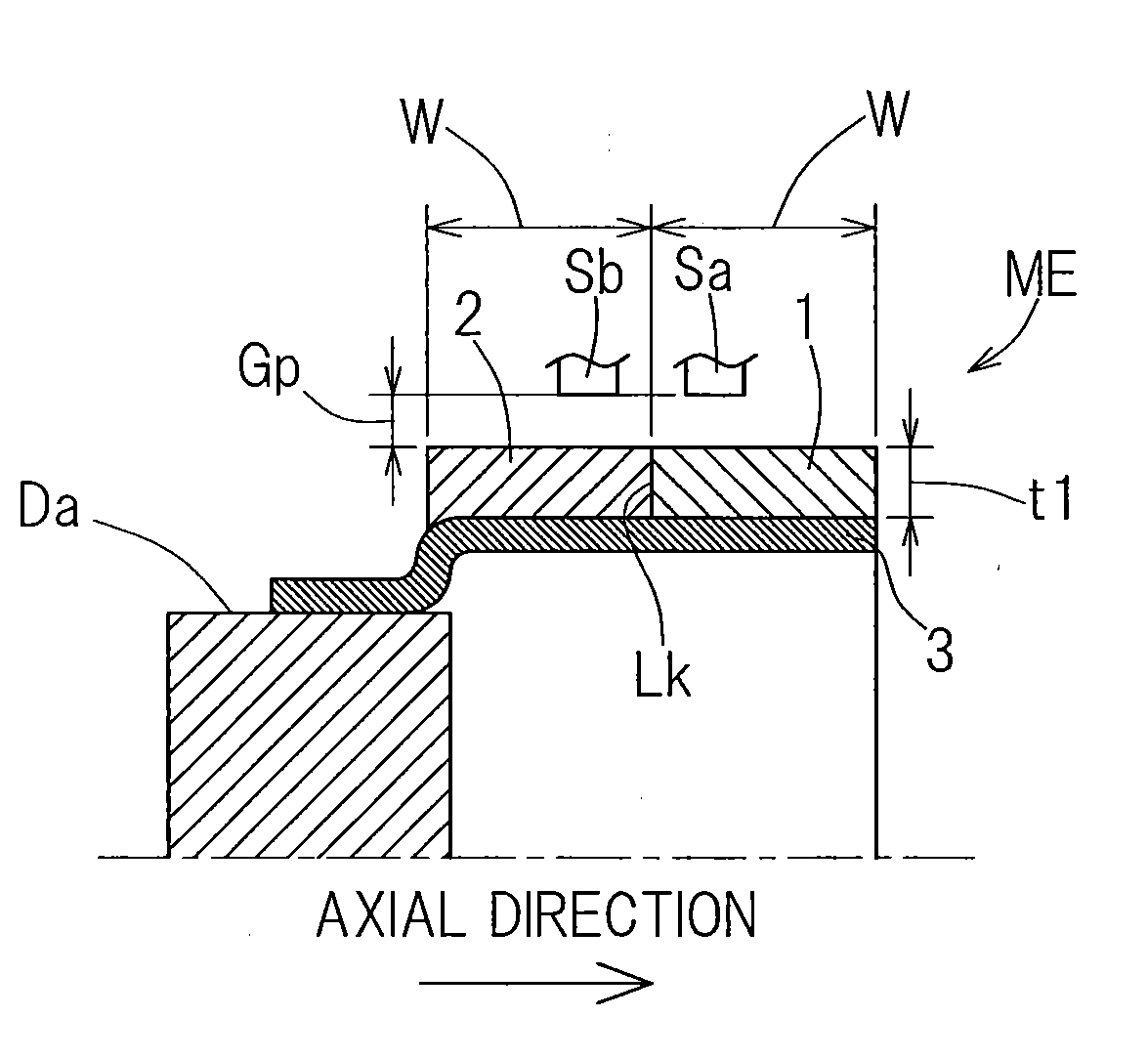
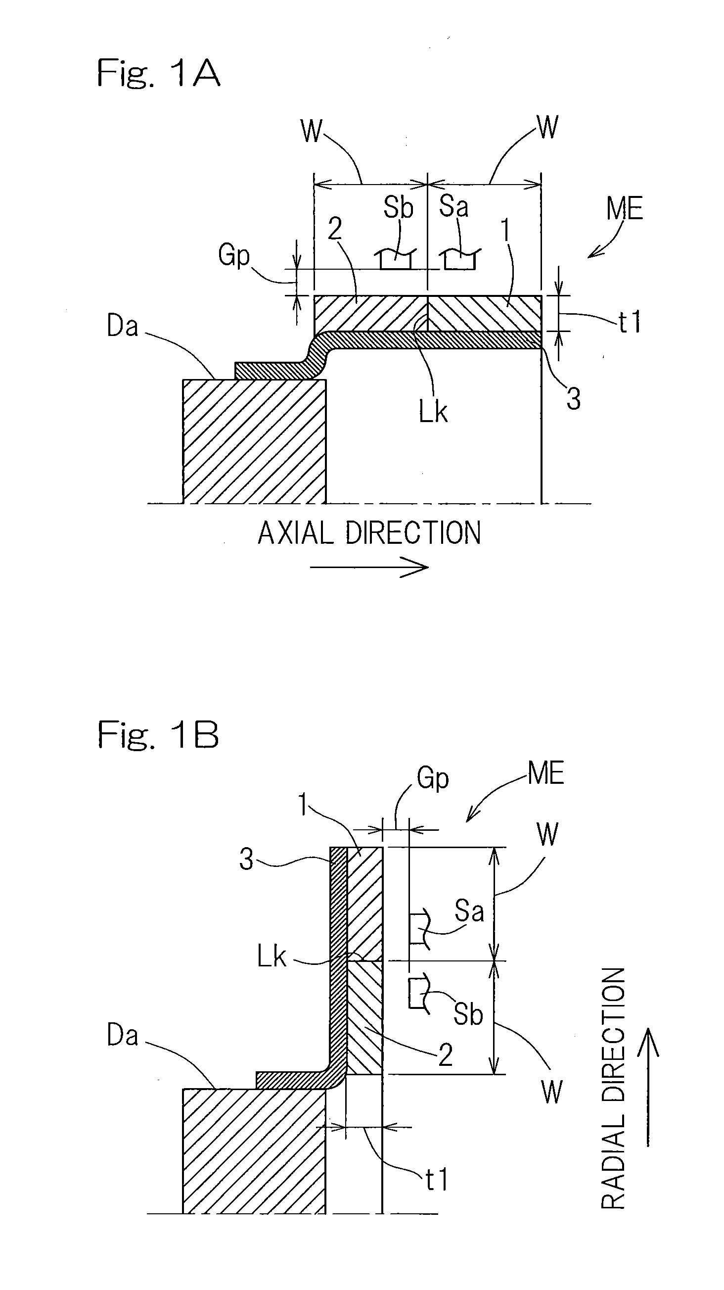
[0089]the present invention will be described in connection with FIGS. 1A and 1B, and FIG. 2 showing diagrams (A) and (B). A magnetic encoder according to this embodiment may be used, for example, to detect rotation, rotational angles, and linear movements of various devices.

[0090]As shown in FIGS. 1A and 1B, a magnetic encoder ME includes plural rows of annular magnetic encoder tracks 1, 2 that are arranged adjacent to each other and are formed integrally with the magnetic encoder ME. The magnetic encoder tracks 1, 2 are disposed on a disc-shaped (FIG. 1B) or cylindrical (FIG. 1A) core 3 such that the magnetic encoder tracks 1, 2 are arranged coaxially and adjacent to each other on a surface of the core 3. As shown in FIG. 1B, a magnetic encoder ME that includes, for example, a magnetized, axial-type, annular magnetic body may be attached to an outer peripheral surface Da of, for example, a rotational raceway member of a bearing, with a cylindrical segment of the core 3 being force...

second embodiment

[0101]The second embodiment through the sixteenth embodiment of the present invention will be hereinafter described. Note that those features corresponding to the features already described with reference to the preceding embodiments will be given the same reference signs and will not be described. In the discussion of a given configuration where only certain features are described, the remaining non-described features should be considered as the same as those already described with reference to the preceding embodiments. Also note that beside the combinations of the features described in detail with reference to a certain embodiment, various embodiments themselves can be partially combined with each other unless such combinations are inoperable.

[0102]FIGS. 3A and 3B show the second embodiment. A magnetic encoder as shown in FIGS. 3A and 3B includes plural rows (two rows in the illustrated example) of magnetic encoder tracks 1, 2 that are arranged adjacent to each other and are form...

third embodiment

[0103]As in the third embodiment shown in FIGS. 4A, 4B and 5, the magnetic encoder ME may include three or more rows of magnetic encoder tracks that are arranged adjacent to each other and are formed integrally with the magnetic encoder, such. For example, the magnetic encoder ME may include a plurality of Z tracks. Use of the resulting signals enables more intricate detection of rotation.


PUM


Abstract

Provided is a magnetic encoder which includes plural rows of magnetic encoder tracks. One magnetic encoder track of the magnetic encoder tracks includes magnetic pattern magnetized thereto to generate signals of equal pitch for detection of rotation. The magnetized magnetic pattern includes N poles and S poles arranged in alternate fashion. The magnetic encoder is configured to be employed spaced through an air gap from sensors that read magnetic signals of the respective magnetic encoder tracks. The magnetic encoder track is configured such that the magnetic pattern thereof acting on position of the corresponding sensor is, under the interference of magnetism of the plural rows of magnetic encoder tracks, detected by the corresponding sensor as an equal pitch magnetic pattern.

Description

CROSS REFERENCE TO THE RELATED APPLICATIONS[0001]This application is based on and claims the Convention priority to a Japanese patent application No. 2010-127768, filed Jun. 3, 2010, the entire disclosure of which is herein incorporated by reference as a part of this application.BACKGROUND OF THE INVENTION[0002]1. Field of the Invention[0003]The present invention relates to a magnetic encoder which may be used to detect rotation, rotational angles, and linear movements of various devices.[0004]2. Description of Related Art[0005]A technique that belongs to the field of bearing elements is disclosed which makes use of magnetic sensors arranged in the form of a line to obtain interpolated pulse signals (see the Patent Documents 1 and 2 listed below). A technique is disclosed which makes use of a magnetic drum having different numbers of magnetic pole pairs per complete rotation and of a plurality of magnetic sensors to calculate absolute angles (see the Patent Document 3 listed below)....

Claims


Application Information

Patent Timeline
Patent Type & Authority Applications(United States)
IPC IPC(8): G01B7/30
CPCG01D5/2451G01D5/24438G01D2205/80
Inventor TAKAHASHI, TORUUENO, SHINTAROUDESBIOLLES, PASCALPETERSCHMITT, CYRIL
Owner NTN CORP
Why Eureka
Try Eureka