
Telescope optical system and optical device provided therewith

a technology of optical system and optical device, which is applied in the field of telescope optical system, can solve the problems of insufficient balance between axial chromatic aberration and lateral chromatic aberration in all systems

Active Publication Date: 2013-03-14
NIKON CORP
View PDF12 Cites 4 Cited by
  • Summary
  • Abstract
  • Description
  • Claims
  • Application Information

AI Technical Summary

Benefits of technology

The present invention is about a telescope optical system that can correct various aberrations, such as axial chromatic aberration and lateral chromatic aberration, to a satisfactory level. Additionally, the patent text describes an optical device that includes this telescope optical system.

Problems solved by technology

However, in a conventional telescope optical system in which a diffractive optical element is used in each of the objective lens system and the eyepiece lens system as described above, the axial chromatic aberration and the lateral chromatic aberration are not sufficiently corrected in a balanced manner in all of the systems.

Method used


Image

  • Telescope optical system and optical device provided therewith
  • Telescope optical system and optical device provided therewith
  • Telescope optical system and optical device provided therewith

Examples


example 1

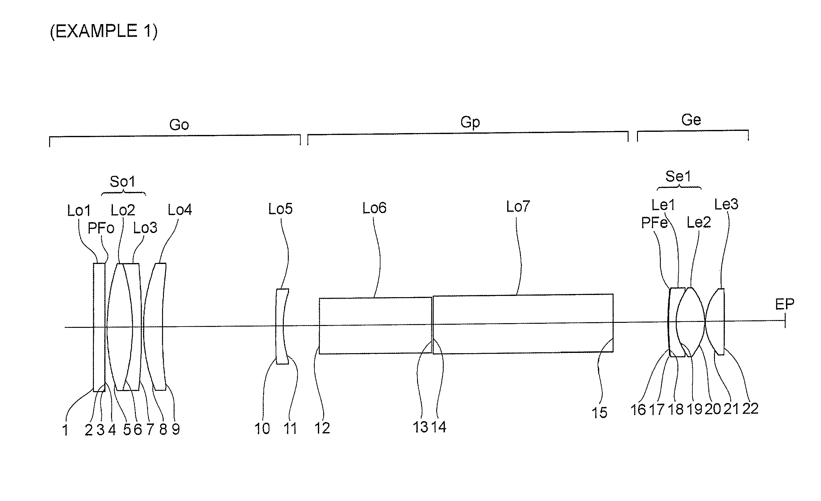
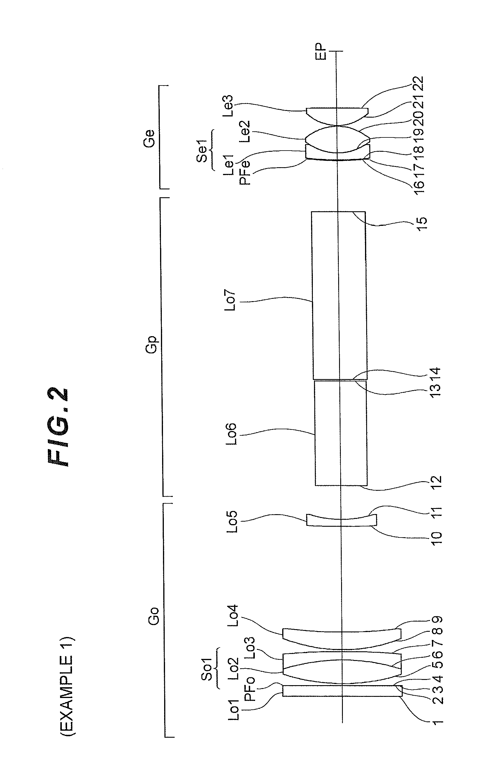
[0075]The telescope optical system according to example 1 will now be described with reference to FIGS. 2 through 4 and Table 1. As shown in FIG. 2, the telescope optical system according to example 1 has, arranged in sequence along the optical axis in order from the object, an objective lens system Go, an upright optical system Gp, and an eyepiece lens system Ge.

[0076]The objective lens system Go has, arranged along the optical axis in order from the object, a parallel flat plate Lo1, a cemented lens So1 comprising cementing of a lens Lo2 having positive refractive power and a lens Lo3 having negative refractive power, a lens Lo4 having positive refractive power, and a lens Lo5 having negative refractive power. The cemented lens So1 is a cemented lens having positive refractive power overall. The upright optical system Gp has prisms Lo6, Lo7.

[0077]The eyepiece lens system Ge has, arranged along the optical, axis in order from the object, a cemented lens Se1 comprising cementing of ...

example 2

[0084]A description will now be given for a telescope optical system according to example 2 with reference to FIGS. 5 through 7 and Table 2. As shown in FIG. 5, the telescope optical system according to example 2 has, arranged in sequence along the optical axis in order from the object, an objective lens system Go, an upright optical system Gp, and an eyepiece lens system Ge.

[0085]The objective lens system Go has, arranged along the optical axis in order from the object, a cemented lens So1 comprising cementing of parallel flat plates Lo1, Lo2; a cemented lens So2 comprising cementing of a lens Lo3 having positive refractive power and a lens Lo4 having negative refractive power; a lens Lo5 having positive refractive power; and a lens Lo6 having negative refractive power. The cemented lenses So1, So2 are cemented lenses having positive refractive power overall. The upright optical system Gp has prisms Lo7, Lo8.

[0086]The eyepiece lens system Ge has, arranged along the optical axis in ...

example 3

[0092]A description will now be given for a telescope optical system according to example 3 with reference to FIGS. 8 through 10 and Table 3. As shown in FIG. 8, the telescope optical system according to example 3 has, arranged in sequence along the optical axis in order from the object, an objective lens system Go, an upright optical system Gp, and an eyepiece lens system Ge.

[0093]The objective lens system Go has, arranged along the optical axis in order from the object, a cemented lens So1 comprising cementing of a lens Lo1 having positive refractive power and a lens Lo2 having negative refractive power; a lens Lo3 having positive refractive power; and a lens Lo4 having negative refractive power. The cemented lens Sol is a cemented lens having positive refractive power overall. The upright optical system Gp has prisms Lo5, Lo6.

[0094]The eyepiece lens system Ge has, arranged along the optical axis in order from the object, a cemented lens Se1 comprising cementing of a lens Le1 havi...


PUM


Abstract

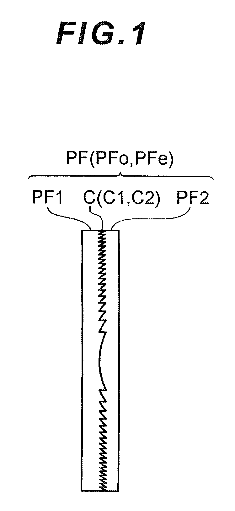
A telescope optical system having an objective lens system and an eyepiece lens system; wherein: the objective lens system includes a multi-layer-type diffractive optical element (PFo), and cemented lenses (So1) provided with a lens having positive refractive power and a lens having negative refractive power; the eyepiece lens system includes a multi-layer-type diffractive optical element (PFe), and cemented lenses (Se1) provided with a lens having negative refractive power and a lens having positive refractive power; and the condition represented by: 2≦|(Po / FNO) / {Pe / (θ×m)}|≦15 is satisfied, where Ko represents the power of the objective lens system, Kodoe represents the power of the diffractive optical element (PFo) of the objective lens system, and Po is defined as Po=Kodoe / Ko; Ke represents the power of the eyepiece lens system, Kedoe represents the power of the diffractive optical element (PFe) of the eyepiece lens system, and Pe is defined as Pe=Kedoe / Ke; and FNO represents the F-number of the objective lens system, θ represents the real field of view of the telescope optical system, and m represents the magnification of the telescope optical system.

Description

TECHNICAL FIELD[0001]The present invention relates to a telescope optical system used for binoculars, telescopes, and similar devices; and an optical device comprising the optical system.TECHNICAL BACKGROUND[0002]A normal telescope optical system comprises, in order from an object, an objective lens system and an eyepiece lens system. An Image of a distant object is formed by the objective lens system on the focal plane thereof, and the formed image is magnified by the eyepiece lens system and viewed.[0003]The objective lens system generally includes a cemented lens comprising cementing of a lens having positive refractive power and a lens having negative refractive power. The cemented lens generates and cancels out positive and negative aberrations, thereby correcting axial chromatic aberration. The eyepiece lens system generally comprises two or more lenses, and corrects lateral chromatic aberration through setting an appropriate spacing between the lenses. Alternatively, in an in...

Claims


Application Information

Patent Timeline
IPC IPC(8): G02B23/00
CPCG02B5/1895G02B23/00G02B27/4211G02B27/0056G02B27/0037G02B5/18G02B13/02G02B23/18
Inventor MATSUMOTO, MIHO
Owner NIKON CORP
Learn More