
Laser Scan Unit Housing for an Imaging Device

a scanning device and laser scanner technology, applied in the direction of instruments, inking apparatus, electrographic processes, etc., can solve the problems of thermal plastic housings that shrink non-uniformly, fuser assemblies, laser scanner motors and other printer components and assemblies may create heat, and the need for assembly adjustment mechanisms

Active Publication Date: 2013-03-21
LEXMARK INT INC
View PDF4 Cites 11 Cited by
  • Summary
  • Abstract
  • Description
  • Claims
  • Application Information

AI Technical Summary

Benefits of technology

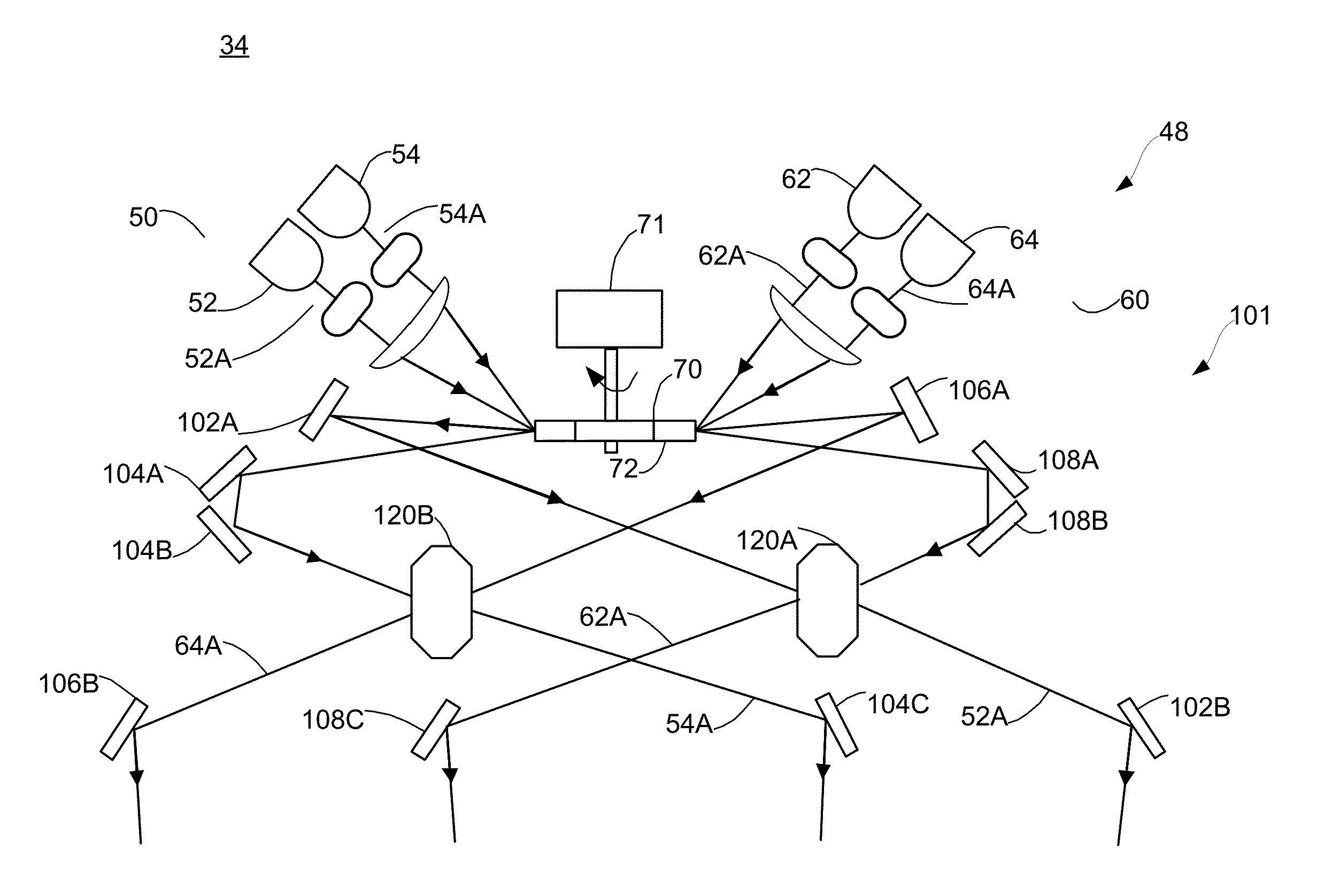
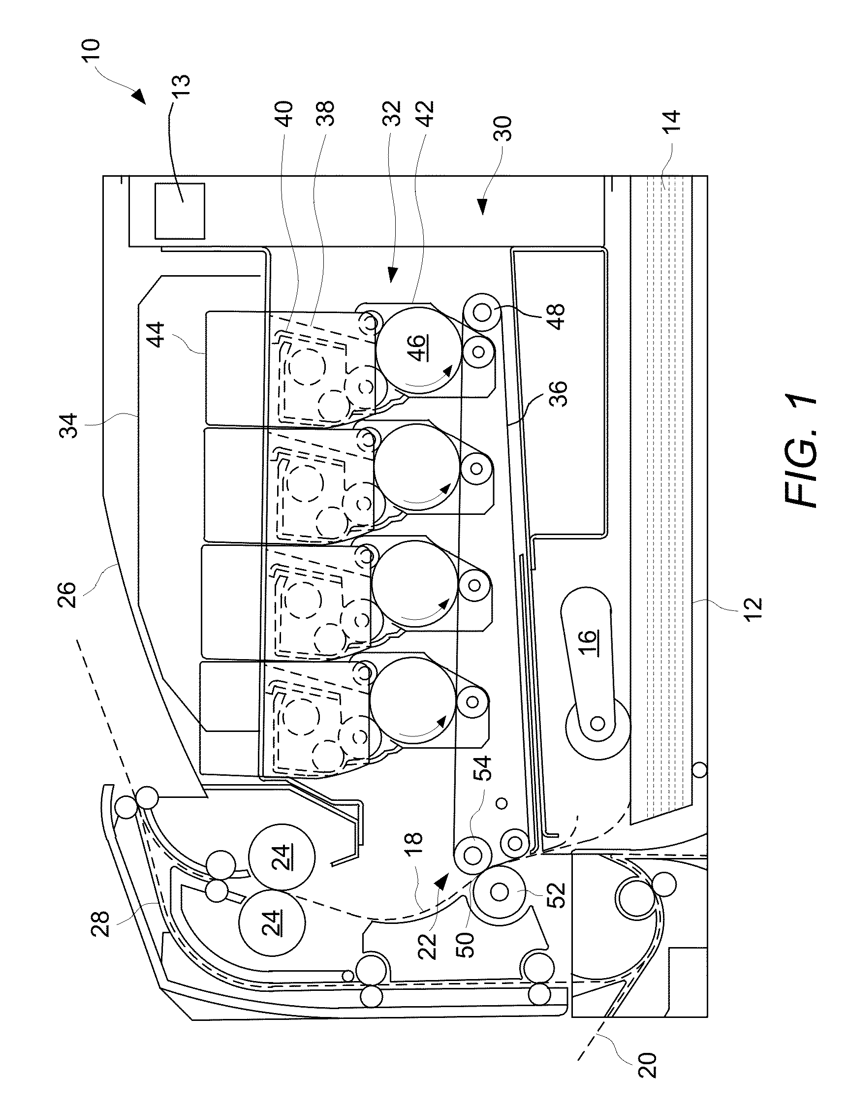
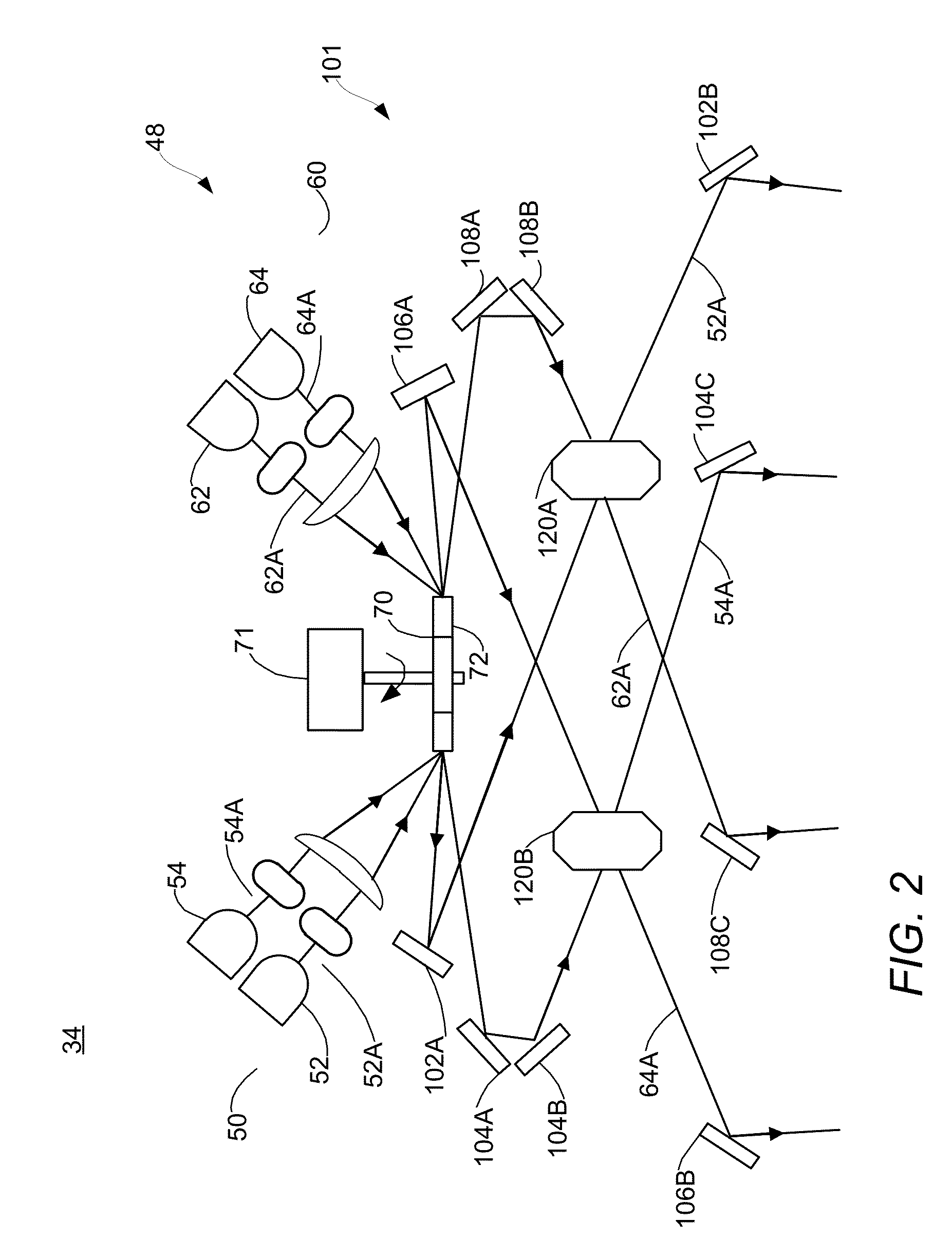
The patent text describes a new laser scanner for an imaging device. The scanner has reduced parts-to-parts variation, which means it works more consistently and better. The scanner includes a mirror and light sources that reflect light beams to create a scan pattern. The scanner also has an optical assembly with a stationary mirror and a lens to form an optical path for the reflected light beams. The scanner is enclosed in a housing which is made from metal and formed through a deep-d Draw process. The housing has mounting surfaces that support the mirror and lens of the optical assembly. The technical effect of this patent is to provide a more reliable and consistent laser scanner for better quality imaging.

Problems solved by technology

Such thermoplastic housings disadvantageously shrink non-uniformly during the molding and subsequent cooling process in the manufacture of the housing.
The inconsistencies associated with the molding and cooling of these critical parts creates two primary issues.
First, part-to part dimensional variation of features for mounting sensitive optical components, such as mirrors and lenses, creates the need for assembly adjustment mechanisms during production as well as additional components.
Second, during normal operation of electrophotographic printers, the fuser assembly, the laser scanner motor and other printer components and assemblies may create heat.
The complex shape and features of the housing design, with a multitude of flow disruptions and directions, does not expand uniformly when heated, causing the part to warp or change shape along with the absolute expansion of the housing.
This change of size and shape of the housing, which locates the critical laser pointing and focal elements, creates print quality issues associated with change of spot size and location of the laser image on the pc drum, primarily color to color registration of the four color planes (CMYK).

Method used


Image

  • Laser Scan Unit Housing for an Imaging Device
  • Laser Scan Unit Housing for an Imaging Device
  • Laser Scan Unit Housing for an Imaging Device

Examples


Embodiment Construction

[0025]The following description and drawings illustrate embodiments sufficiently to enable those skilled in the art to practice the present invention. It is to be understood that the disclosure is not limited to the details of construction and the arrangement of components set forth in the following description or illustrated in the drawings. The invention is capable of other embodiments and of being practiced or of being carried out in various ways. For example, other embodiments may incorporate structural, chronological, electrical, process, and other changes. Examples merely typify possible variations. Individual components and functions are optional unless explicitly required, and the sequence of operations may vary. Portions and features of some embodiments may be included in or substituted for those of others. The scope of the application encompasses the appended claims and all available equivalents. The following description is, therefore, not to be taken in a limited sense, ...


PUM


Abstract

A housing for the scan unit printhead of an imaging device. The housing is substantially bowl shaped having a plurality of mounting surfaces extending inwardly toward a central region of the housing. The housing is constructed from a metal composition. The scan unit includes a plurality of light sources and an optical assembly operatively coupled thereto. The housing mounting surfaces support components of the optical assembly using an adhesive, without additional mounting hardware.

Description

CROSS REFERENCES TO RELATED APPLICATIONS[0001]The present application is related to and claims priority from U.S. patent application 61 / 537,043, filed Sep. 20, 2011, entitled, “Laser Scan Unit Housing for an Imaging Device,” the contents of which are incorporated herein by reference its entirety.STATEMENT REGARDING FEDERALLY SPONSORED RESEARCH OR DEVELOPMENT[0002]None.REFERENCE TO SEQUENTIAL LISTING, ETC.[0003]None.BACKGROUND[0004]1. Field of the Disclosure[0005]Example embodiments of the present disclosure relate generally to a laser scan unit for an image scanning device, and more particularly to a housing for a laser scan unit having a metal construction and simplified mounting mechanisms for the optical components of the scan unit.[0006]2. Description of the Related Art[0007]Multibeam and single beam laser scanners typically include a housing for holding the scanner's optical components that is constructed from a thermoplastic. Such thermoplastic housings disadvantageously shrin...

Claims


Application Information

Patent Timeline
IPC IPC(8): B41J2/435
CPCG02B26/123B41J2/473G02B26/121G03G15/04036G03G15/043H05K9/0007H05K9/0049
Inventor HUDSON, RANDALL LEEROWE, JASON LEE
Owner LEXMARK INT INC
Learn More