
Vacuum insulating glass (VIG) unit pump-out tube protecting techniques, and/or vig units incorporating the same

Inactive Publication Date: 2013-03-28
GUARDIAN GLASS LLC
View PDF2 Cites 45 Cited by
  • Summary
  • Abstract
  • Description
  • Claims
  • Application Information

AI Technical Summary

Benefits of technology

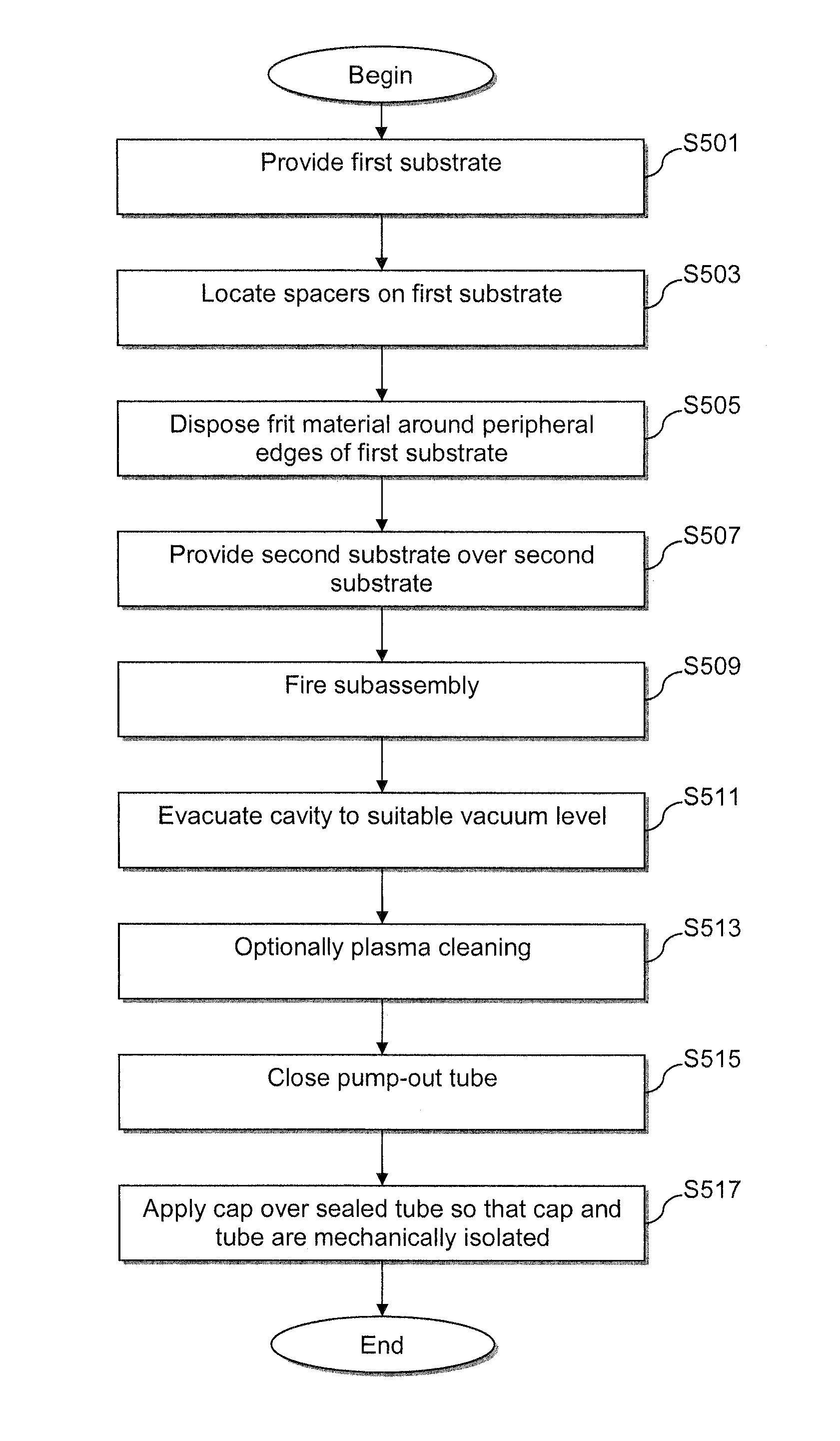
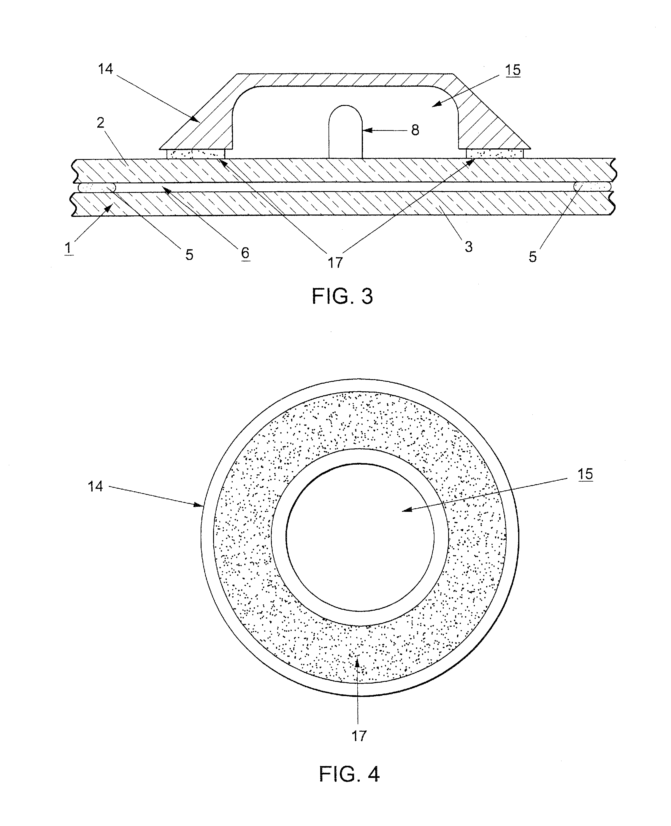
The patent text describes a vacuum insulating glass (VIG) unit and a conventional vacuum pump-out tube. The technical effect of the patent text is to provide an improved technique for protecting the pump-out tube in VIG units by using a cap that is mechanically isolated from the substrate and secured to the outer major surface of the substrate via an adhesive. This helps to prevent damage to the pump-out tube and maintain low pressure space between the substrates. The cap can be easily applied and is not limited by the lifespan of silicone-based adhesives.

Problems solved by technology

Because the tube it glass, it frequently can be quite fragile.
Furthermore, because the glass tube extends above the outer surface of the substrate, it oftentimes is susceptible to damage.
Unfortunately, however, this technique has several drawbacks.
The mechanical bonding between the cap and the pump-out tube, however, makes the tube susceptible to damage as a result of external mechanical manipulation of the cap (e.g., as a result of applied pressure, bumping, thermal expansion, etc.).
Thus, although the cap is supposed to be protective, it can jostle and sometimes even break the tube.
If the tube is broken, then vacuum will be lost and the VIG unit will be rendered largely inoperative for its intended purposes.
Another drawback relates to the limited lifetime of silicone-based adhesives.
Thus, the silicone could fail after time as a result of its normal product lifecycle.
In such cases, the cap may come off, leaving the pump-out tube largely unprotected.
Still another drawback relates to the difficulty in applying silicon sealants.
Silicone sealants oftentimes are “messy,” leading to potentially difficult or irritating and costly cleanup processes.

Method used


Image

  • Vacuum insulating glass (VIG) unit pump-out tube protecting techniques, and/or vig units incorporating the same
  • Vacuum insulating glass (VIG) unit pump-out tube protecting techniques, and/or vig units incorporating the same
  • Vacuum insulating glass (VIG) unit pump-out tube protecting techniques, and/or vig units incorporating the same

Examples


Embodiment Construction

[0024]Certain embodiments of this invention relate to an improved peripheral or edge seal in a vacuum IG window unit, and / or a method of making the same. “Peripheral” and “edge” seals herein do not mean that the seals are located at the absolute periphery or edge of the unit, but instead mean that the seal is at least partially located at or near (e.g., within about two inches) an edge of at least one substrate of the unit. Likewise, “edge” as used herein is not limited to the absolute edge of a glass substrate but also may include an area at or near (e.g., within about two inches) of an absolute edge of the substrate(s). Also, it will be appreciated that as used herein the term “VIG assembly” refers to an intermediate product prior to the VIG's edges being sealed and evacuation of the recess including, for example, two parallel-spaced apart substrates and a frit. Also, while the frit may be said to be “on” or “supported” by one or more of the substrates herein, this does not mean t...


PUM

PropertyMeasurementUnit
Forceaaaaaaaaaa

Abstract

Certain example embodiments of this invention relate to techniques for protecting the pump-out tubes of vacuum insulating glass (VIG) units. More particularly, certain example embodiments relate to techniques for protecting a pump-out tube of a VIG unit by providing a cap around the tube, with the cap and the tube being mechanically separated from one another. In certain example embodiments, the cap and an outer surface of the substrate in which the pump-out tube is located are connected to one another via an adhesive (e.g., a double-sided tape or other adhesive). The mechanical separation or isolation as between the cap and the tube may help protect the potentially fragile glass pump-out tube, in that forces imparted to the cap preferably would be buffered from and generally not transferred to the tube.

Description

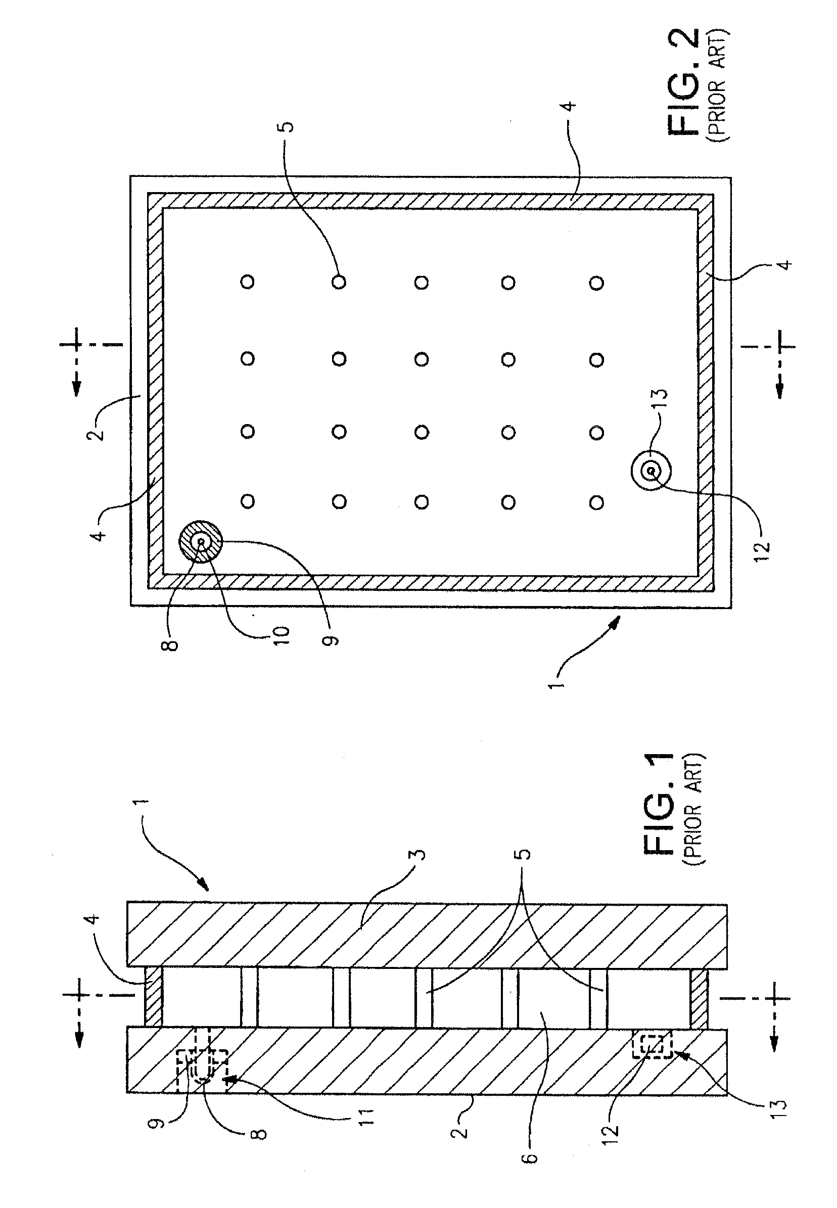
FIELD OF THE INVENTION[0001]Certain example embodiments of this invention relate to techniques for protecting the pump-out tubes of vacuum insulating glass (VIG) units. More particularly, certain example embodiments relate to techniques for protecting a pump-out tube of a VIG unit by providing a cap around the tube, with the cap and the tube being mechanically separated from one another. In certain example embodiments, the cap and an outer surface of the substrate in which the pump-out tube is located are connected to one another via an adhesive (e.g., a double-sided tape or other adhesive).BACKGROUND AND SUMMARY OF EXAMPLE EMBODIMENTS OF THE INVENTION[0002]Vacuum IG units are known in the art. For example, see U.S. Pat. Nos. 5,664,395, 5,657,607, and 5,902,652, the disclosures of which are all hereby incorporated herein by reference.[0003]FIGS. 1-2 illustrate a conventional vacuum IG unit (vacuum IG unit or VIG unit). Vacuum IG unit 1 includes two spaced apart glass substrates 2 an...

Claims


Application Information

Patent Timeline
IPC IPC(8): E06B3/67B32B37/14B32B37/12E06B3/663E06B3/677
CPCE06B3/6775
Inventor JONES, JEFFREY A.
Owner GUARDIAN GLASS LLC
Learn More