Lighting circuit for light emitting element and illumination apparatus including same

Active Publication Date: 2013-03-28
PANASONIC CORP
View PDF2 Cites 8 Cited by
  • Summary
  • Abstract
  • Description
  • Claims
  • Application Information

AI Technical Summary

Benefits of technology

The present invention provides a lighting circuit for a light emitting element that reduces variations in lighting timings when a PWM dimming signal is switched to a next ON period after an OFF period in burst dimming. The circuit maintains the light emitting element to slightly emit a light even during the OFF period of the PWM dimming signal. This results in a faster lighting process and reduces the time required to achieve the desired dimming level. Additionally, the circuit allows for power savings during the turn-off period when burst dimming is not performed.

Problems solved by technology

Since there is a significant variation in the threshold voltage Vth of the light emitting element due to a manufacturing error, lighting timings of different light emitting elements may not the same when the PWM dimming signal is switched to a next ON period.

Method used


Image

  • Lighting circuit for light emitting element and illumination apparatus including same
  • Lighting circuit for light emitting element and illumination apparatus including same
  • Lighting circuit for light emitting element and illumination apparatus including same

Examples


first embodiment

Modification of First Embodiment

[0068]FIG. 5 shows a circuit diagram of a light-emitting-element lighting circuit 22a that is a modification of the lighting circuit 22. The same reference numerals will be given to the same components as those of the lighting circuit 22, and a redundant description thereof will be omitted.

[0069]The lighting circuit 22a includes a minimum current generating circuit C2 instead of the minimum current generating circuit C1. The minimum current generating circuit C2 includes a diode 66 which is a reverse-biased diode connected in parallel with the switching transistor 57. The diode 66 is turned on when the switching transistor 57 is turned off, and has an impedance to flow the minimum current Imin. The diode 66 may be connected in series with other impedance elements such as a resistor for impedance adjustment and the like.

[0070]The lighting circuit 22a has the same configuration and operation as those of the lighting circuit 22 except for the minimum cur...

second embodiment

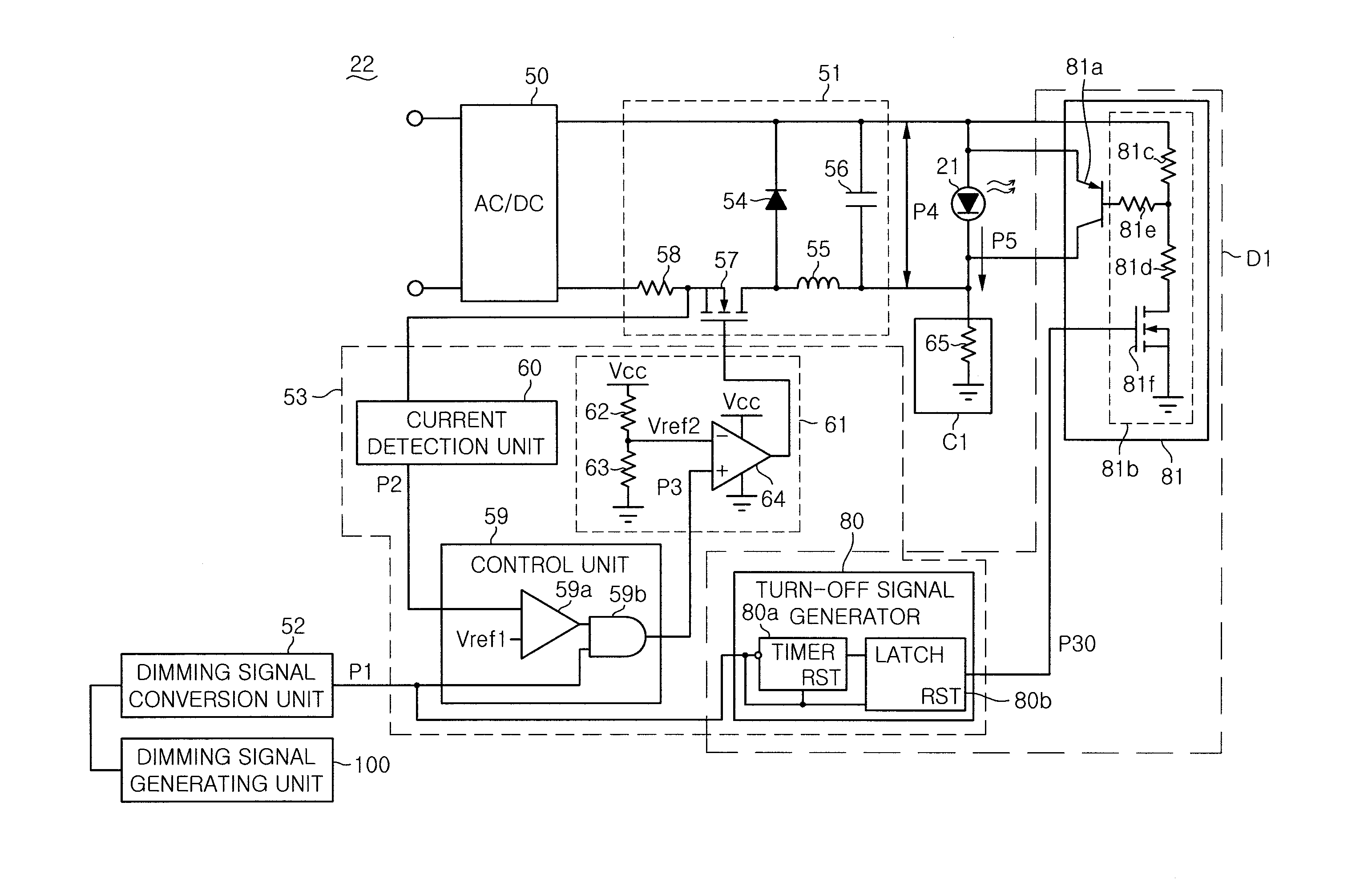
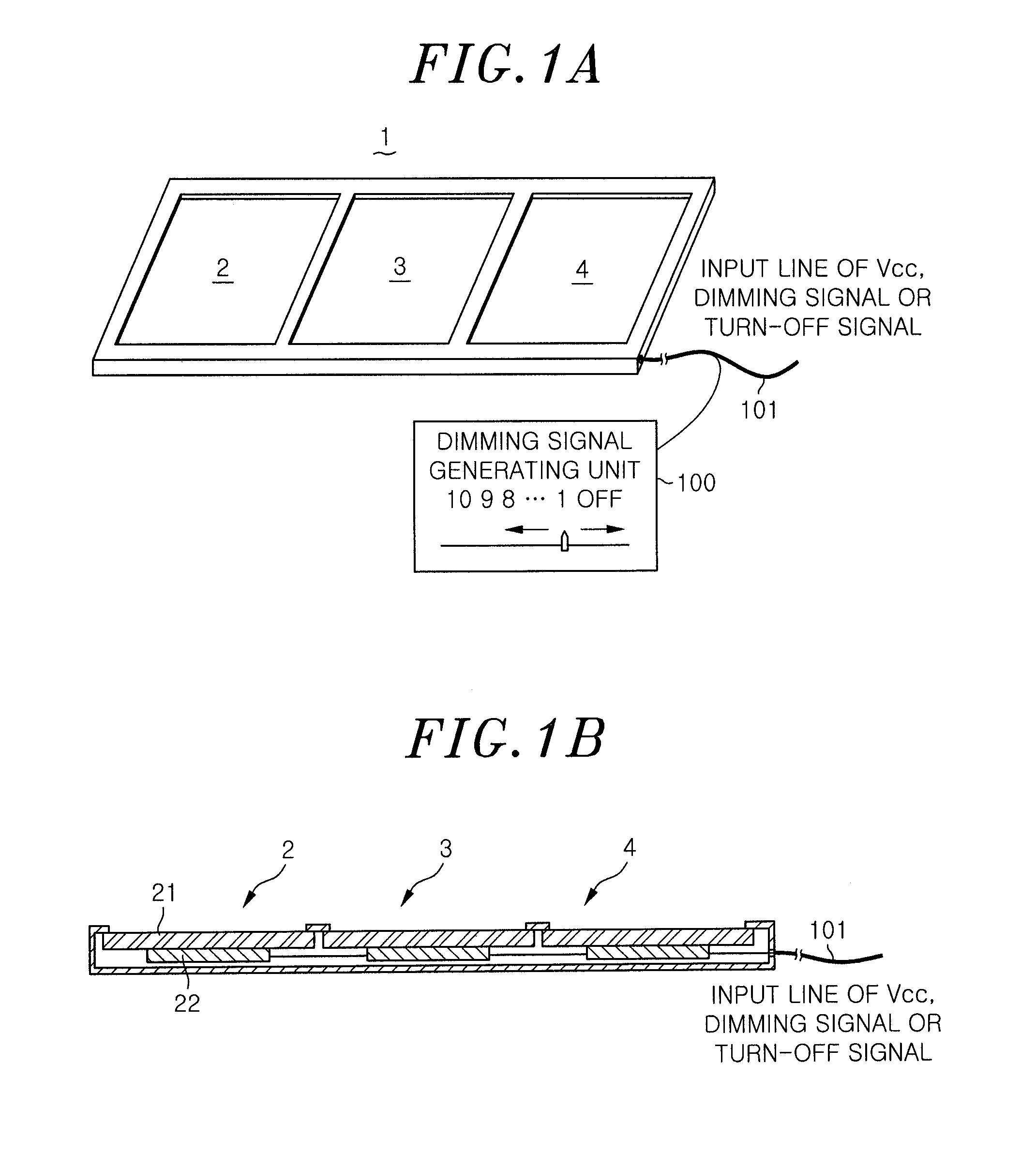
[0072]FIG. 6 is a circuit diagram of a light-emitting-element lighting circuit 22b included in an illumination apparatus in accordance with a second embodiment of the present invention. The lighting circuit 22b has the minimum current Imin to flow by reducing a pulse width of a chopper signal during the OFF period and achieves a rapid lighting of the light emitting element when it is switched to a next ON period. The illumination apparatus of the second embodiment has the same configuration as that of the illumination apparatus 1 (FIG. 1) except for the light emitting element lighting circuit 22b. In the lighting circuit 22b, the same reference numerals will be given to the same components as those of the light emitting element lighting circuit 22, and a redundant description thereof will be omitted.

[0073]The lighting circuit 22b includes the AC / DC unit 50 connected to the commercial AC power source, the power conversion unit 51, the dimming signal conversion unit 52 connected to th...

third embodiment

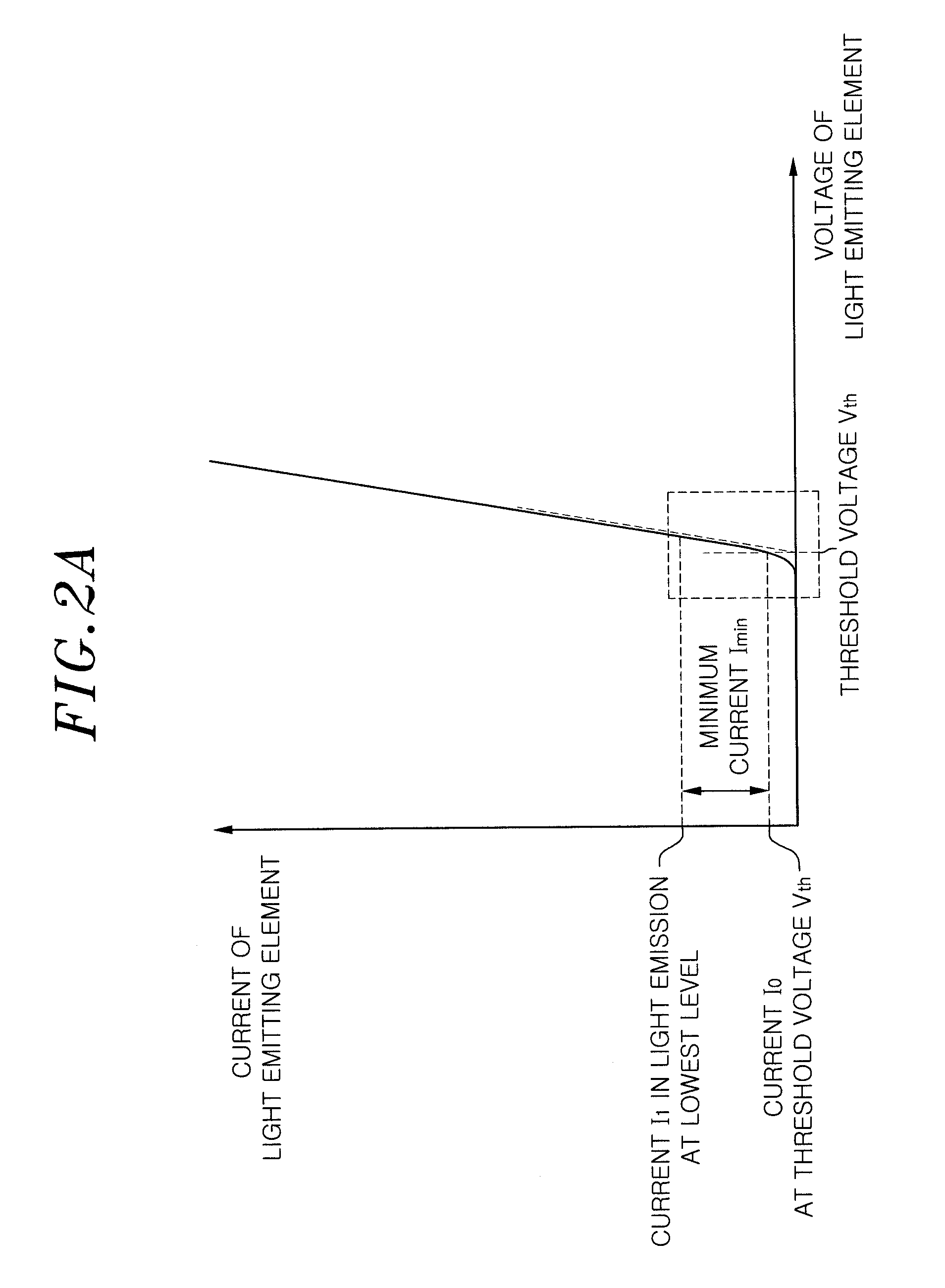
[0081]FIG. 8 is a circuit diagram of a light-emitting-element lighting circuit 22c included in an illumination apparatus in accordance with a third embodiment of the present invention. The illumination apparatus of the third embodiment has the same configuration as that of the illumination apparatus 1 (FIG. 1) except for the lighting circuit 22c. The lighting circuit 22c includes a constant voltage circuit which operates only during the OFF period, and has the minimum current Imin to flow in the light emitting element 21 to achieve rapid lighting of the light emitting element when it is switched to a next ON period. In the light emitting element lighting circuit 22c, the same reference numerals will be given to the same components as those of the light emitting element lighting circuit 22, and a redundant description thereof will be omitted.

[0082]The lighting circuit 22c includes the AC / DC unit 50 connected to the commercial AC power source, the power conversion unit 51, the dimming...


PUM


Abstract

A light-emitting-element lighting circuit for dimming a light emitting element having a diode characteristic by a PWM dimming signal is provided. The lighting circuit includes a dimming signal conversion unit configured to generate the PWM dimming signal having a duty ratio corresponding to an emission level specified by an input dimming signal. The lighting circuit further includes a minimum current generating circuit configured to flow a minimum current during an OFF period of the PWM dimming signal generated by the dimming signal conversion unit such that a voltage greater than a threshold voltage designed to allow the light emitting element to emit a light is applied to the light emitting element, and the light emitting element emits a light of a brightness equal to or less than a lowest emission level specified by the dimming signal.

Description

FIELD OF THE INVENTION[0001]The present invention relates to a lighting circuit for a light emitting element such as an organic electroluminescence (EL) element and an illumination apparatus including the lighting circuit.BACKGROUND OF THE INVENTION[0002]Conventionally, there is known a lighting circuit configured to generate a PWM dimming signal corresponding to an emission level specified by a dimming signal, and perform the dimming control by using a light emitting element such as an organic EL element.[0003]For example, Japanese Patent Application Publication No. 2011-60703 discloses a lighting circuit configured to perform a so-called burst dimming to stop the emission of the light emitting element during an OFF period of the PWM dimming signal.[0004]The light emitting element such as an organic EL element having a diode characteristic begins to emit a light when an applied voltage exceeds a threshold voltage Vth. In the burst dimming performed by the apparatus described in Jap...

Claims


Application Information

Patent Timeline
Patent Type & Authority Applications(United States)
IPC IPC(8): H05B37/02H05B44/00
CPCH05B33/0896H05B45/60Y02B20/30
Inventor OKAWA, MASANAOKONISHI, HIROFUMIHAYASHI, YOHEIMISHIMA, MASANORI
Owner PANASONIC CORP
Why Eureka
Try Eureka