
Durable drawer retainer apparatus and method of use

a technology of drawer retainer and drawer slide, which is applied in the direction of drawers, furniture parts, domestic applications, etc., can solve the problems of reducing so as to prolong the usable life of the drawer slide assembly

Active Publication Date: 2013-03-28
HARDWARE RESOURCES
View PDF22 Cites 37 Cited by
  • Summary
  • Abstract
  • Description
  • Claims
  • Application Information

AI Technical Summary

Benefits of technology

The patent describes a drawer slide assembly with a stay closed mechanism. This mechanism is an inexpensive alternative to previous drawer slide assemblies that have a longer lifespan and are easier to use. The front mounted and adjustable mechanism keeps the drawer closed and prevents it from opening unintentionally. This patent provides a cost-effective solution for improving the functionality and durability of drawer slide assemblies.

Problems solved by technology

As a result, drawers are often closed rapidly and with excess force and have a tendency to rebound when closed.
In cabinetry installed in mobile homes, recreational vehicles, or boats, the low friction provided by the rails allows unintentionally opening drawers during vehicle movement.
The device requires a component on each slide member and the latch arm is susceptible due to constant deformation and frictional forces.
Further, the force applied by the soft sequencing latch is not adjustable.
The force applied by the stop / anti-rebound mechanism is not adjustable.
The device is prone to wear and deteriorates over time due to friction and repeated deformation.
The device is not adjustable.
The strike is deformable and so is prone to wear due to frictional forces and repeated deformation.

Method used


Image

  • Durable drawer retainer apparatus and method of use
  • Durable drawer retainer apparatus and method of use
  • Durable drawer retainer apparatus and method of use

Examples


Embodiment Construction

[0024]In the descriptions that follow, like parts are marked throughout the specification and drawings with the same numerals, respectively. The drawing figures are not necessarily drawn to scale and certain figures may be shown in exaggerated or generalized form in the interest of clarity and conciseness.

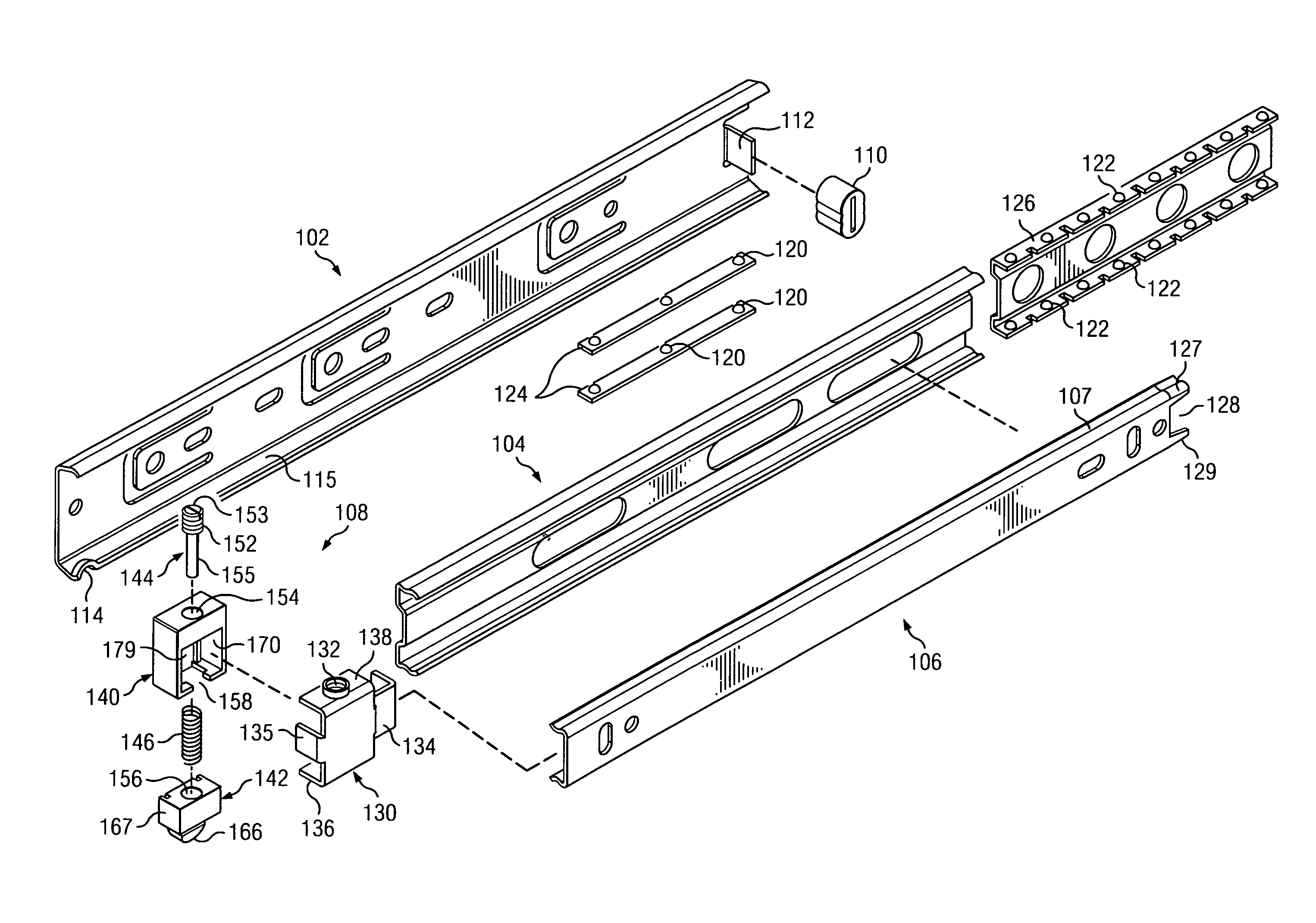
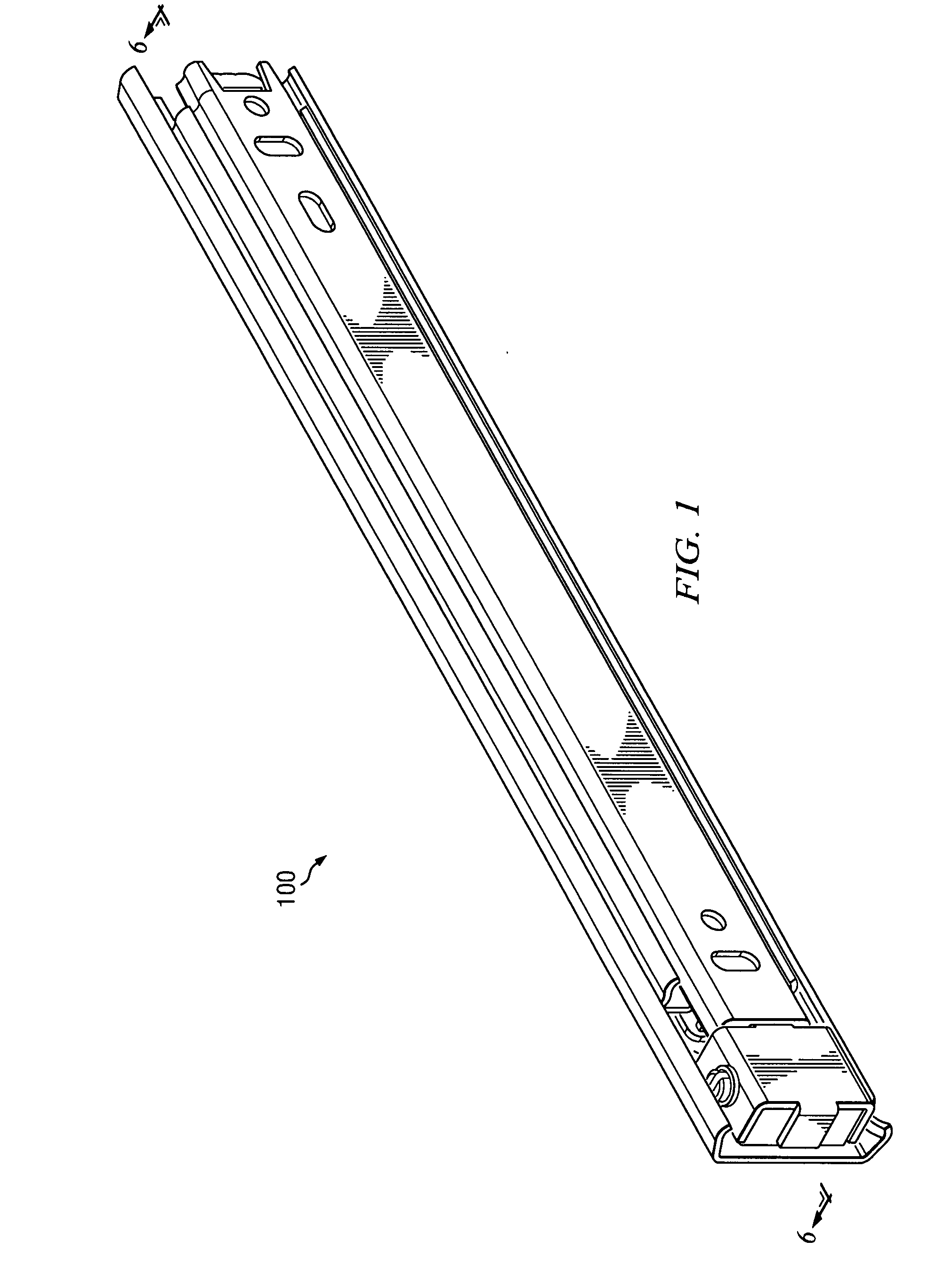
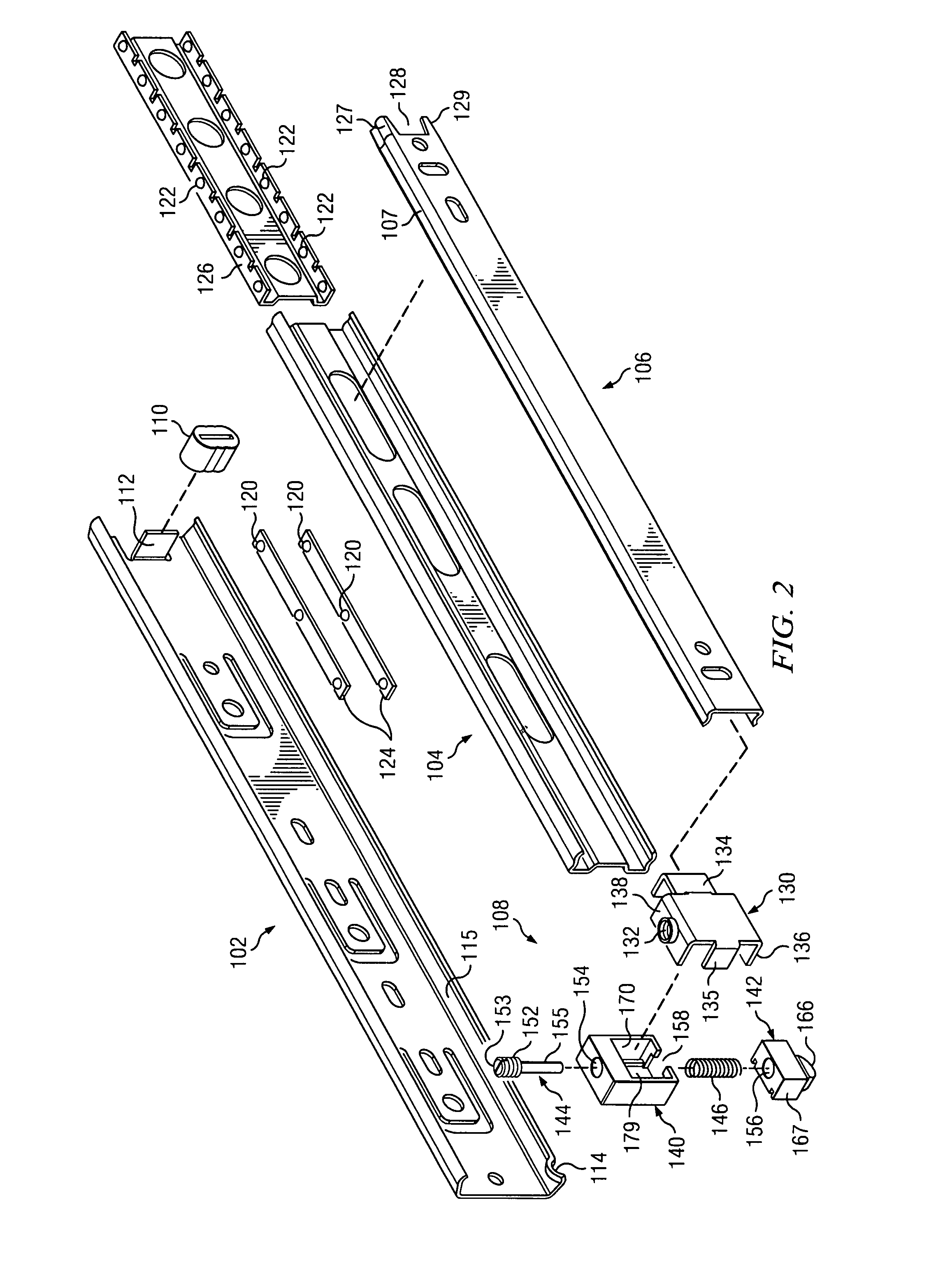
[0025]Referring to FIGS. 1 and 2, drawer slide assembly 100 is comprised of fixed member 102, middle member 104, drawer member 106, and drawer retainer mechanism 108. Each member 102, 104, and 106 of drawer slide assembly 100 is generally C-shaped and includes a pair of races for housing ball-bearing assemblies. Fixed member 102 is mounted to the inside of the cabinet frame of a furniture piece having a drawer using common attachment hardware such as wood screws. Although three slides are shown, it is understood that a greater or lesser number of slides may be telescopically engaged with one another.

[0026]Proximate the front end of fixed member 102 is raised indention 114 located i...


PUM


Abstract

A full extension ball bearing drawer slide assembly comprised of a fixed member attached to a cabinet piece, a middle member slidingly engaged with the fixed member with a set of linear bearings, a drawer member attached to a drawer piece slidingly engaged with the middle member via a second set of linear bearings, and a drawer retainer mechanism attached to the drawer member and in adjustable contact with the drawer member. The drawer retainer mechanism is comprised of a frame attached to the drawer member, a housing seated in the frame, a detent fitted in the frame and biased by a helical spring adjacent a post. The post has a threaded section engaged with a threaded hole in the frame. The detent, biased by the helical spring on the post, is forced towards the housing by a raised indention in a race of the fixed member.

Description

FIELD OF THE INVENTION[0001]The present invention relates to sliding assemblies for mounting drawers in cabinetry. In particular, the invention relates to extension ball bearing slides with a durable, front mounted, adjustable drawer retainer mechanism which prohibits the inadvertent opening of a closed drawer.BACKGROUND OF THE INVENTION[0002]Drawer slides mounted to cabinets and drawers for slidably moving a drawer in a cabinet are well known in the art. Drawer slides are typically constructed of two or more rails which are telescopically extendable. In standard practice, the outer most rail is the widest and is mounted to the stationary cabinet wall and encloses the inner rails. The innermost rail is typically mounted on the side or underneath the drawer piece. The rails usually incorporate ball bearings mounted in retainers and seated in races formed in the sides of the rails so that the rails may slide with respect to each other. This low friction provided by the rails allows th...

Claims


Application Information

Patent Timeline
Patent Type & Authority Applications(United States)
IPC IPC(8): A47B88/04A47B88/49A47B88/493
CPCA47B88/10A47B2210/0018A47B88/08A47B2088/0474A47B2210/0081A47B2088/4675A47B88/49A47B88/493
Inventor LOWE, MARK JEFFREYNUCKOLLS, GRANT
Owner HARDWARE RESOURCES
Learn More