Low offset hingeless rotor with pitch change bearings

a hingeless rotor, low offset technology, applied in the direction of liquid fuel engines, vessel construction, marine propulsion, etc., can solve the problems of large weight and many parts of the gimbal-style hub

Inactive Publication Date: 2013-03-28
SIKORSKY AIRCRAFT CORP
View PDF4 Cites 19 Cited by
  • Summary
  • Abstract
  • Description
  • Claims
  • Application Information

AI Technical Summary

Problems solved by technology

Further, the gimbal-style hub has ...

Method used


Image

  • Low offset hingeless rotor with pitch change bearings
  • Low offset hingeless rotor with pitch change bearings
  • Low offset hingeless rotor with pitch change bearings

Examples


Embodiment Construction

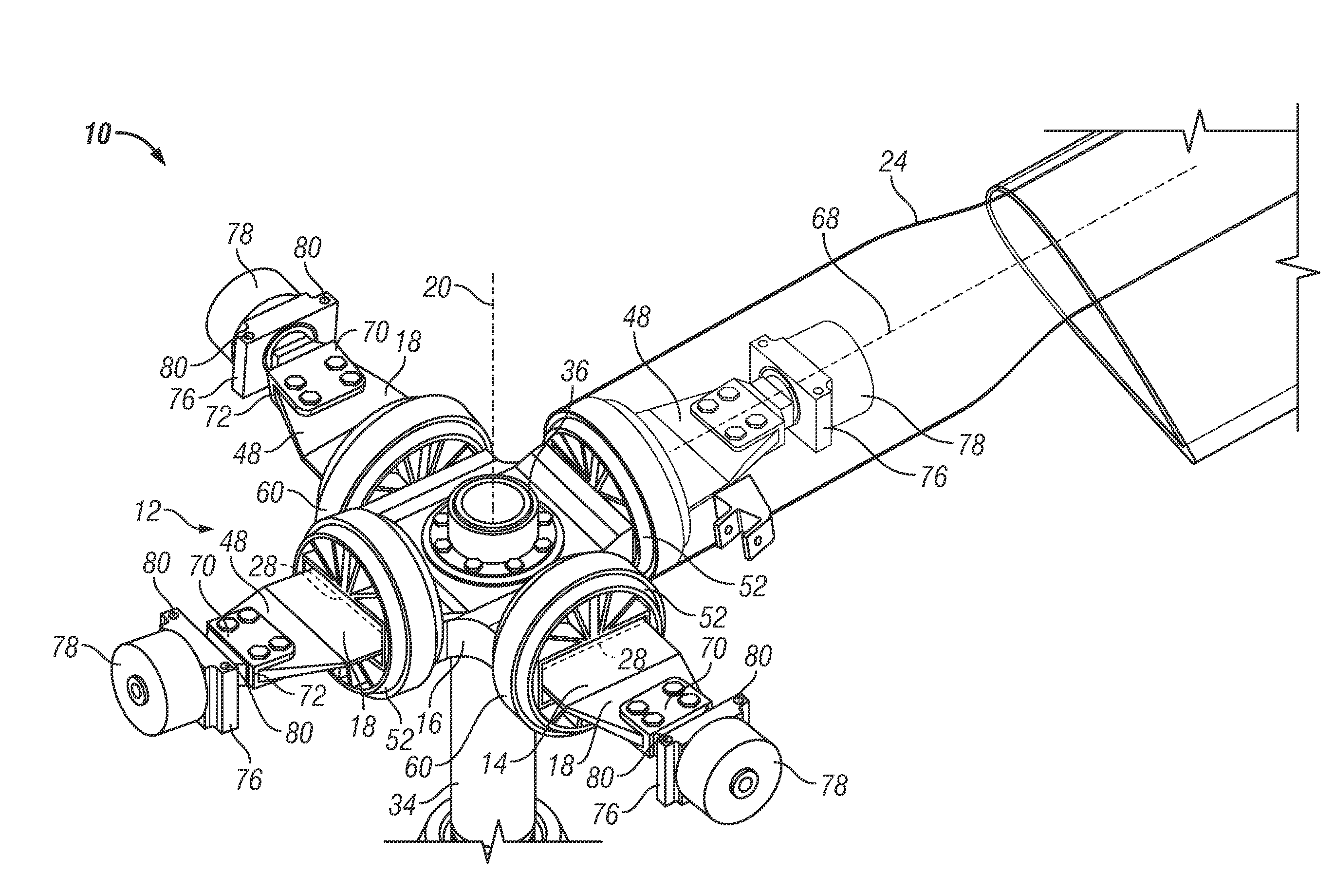
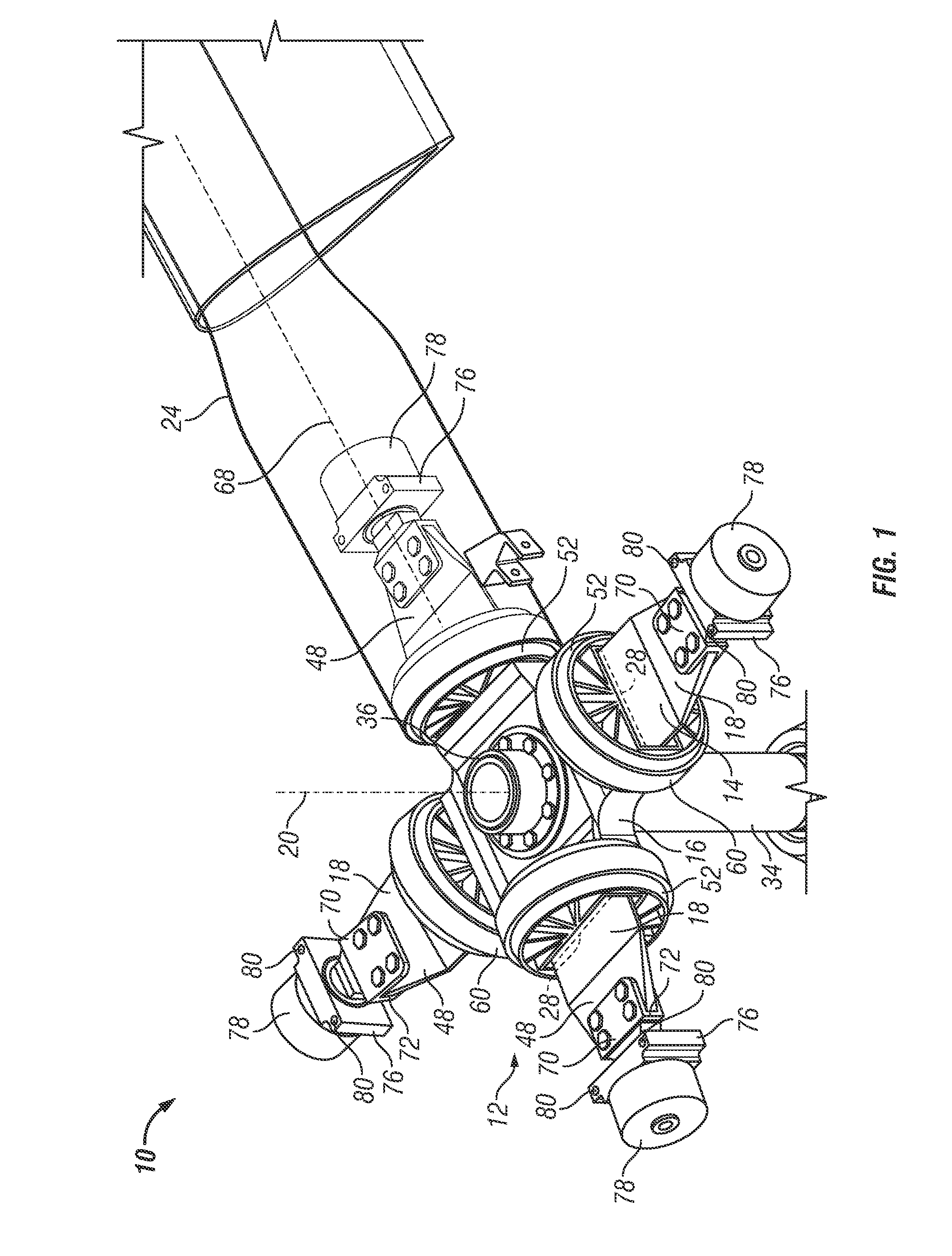
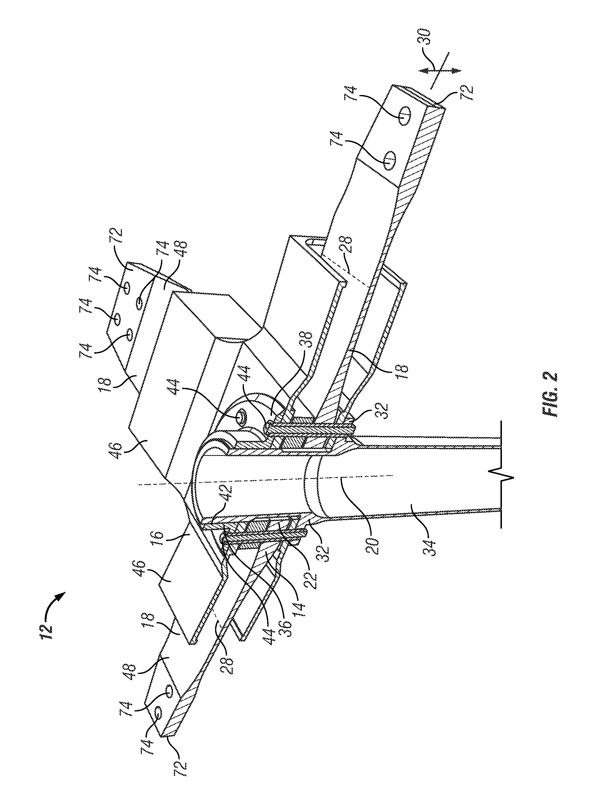
[0017]Referring to FIG. 1, shown is an embodiment of an improved rotor assembly 10. The rotor assembly 10 includes a rotor hub 12, best shown in FIG. 2. The rotor hub 12 includes a yoke 14 surrounded by a spindle 16. In some embodiments, the yoke 14 is constructed of at least one flex beam 18. Each flex beam 18 extends along a diameter of the yoke 14 toward a rotor axis 20. In some embodiments, each flex beam 18 extends across the rotor axis 20 and includes a hub opening 22. Each flex beam 18 is configured to be supportive of an outboard spindle 70, as shown in FIG. 1. Referring again to FIG. 2, to support additional rotor blades 24, additional flex beams 18 can be stacked at the rotor axis 20. For example, as shown, to construct a rotor hub 12 supportive of four rotor blades 24, two flex beams 18 may be stacked and offset at an angle of approximately ninety degrees about the rotor axis 20, though the flex beams 18 may be offset at other suitable angles for dynamic and / or acoustic r...


PUM


Abstract

A hub assembly for a tilt rotor includes a yoke having a plurality of yoke arms located substantially orthogonal to a central axis of the hub assembly. An inboard pitch change bearing assembly substantially surrounds a yoke arm of the plurality of yoke arms. An outboard pitch change bearing assembly is located at the yoke arm. The inboard pitch change bearing assembly and the outboard pitch change bearing assembly are operably connectable with a rotor blade to allow pitch change of the rotor blade relative to the yoke about a pitch change axis.

Description

CROSS-REFERENCE TO RELATED APPLICATIONS[0001]This is a nonprovisonal application of U.S. Provisional Application No. 61 / 307,511, filed on Feb. 24, 2010, the disclosure of which is also incorporated herein by reference.BACKGROUND OF THE INVENTION[0002]The subject matter disclosed herein generally relates to rotors for aircraft use. More specifically, the subject disclosure relates to hub configurations for tilt rotors.[0003]Rotor blades utilized in tilt-rotor aircraft typically must be able to pitch significantly relative to a blade pitch change axis, be capable of allowing flapping motion of the rotor blades, have proper frequency placement, proper kinematic couplings, among other requirements. To meet these requirements in the past, a gimbal-style rotor hub has been utilized as shown in FIG. 7. A gimbal style hub offers the benefit of a low head moment and, consequently, less structure required to support the rotor shaft within the gearbox and less structure required to support the...

Claims


Application Information

Patent Timeline
IPC IPC(8): B64C11/06
CPCB64C11/06B64C27/33B64C27/39B64C27/37B64C27/35
Inventor BASKIN, BRYAN KENNETHWALKER, TODD DAVID
Owner SIKORSKY AIRCRAFT CORP
Why Eureka
Try Eureka