Intravenous Flow Rate Controller

a flow rate controller and flow rate technology, applied in the field of system and method of fluid delivery control, can solve the problems of reducing the rate of drop formation and flow, the rate control clamp is forced to change its adjustment, and the rate to chang

Active Publication Date: 2013-04-04
ICU MEDICAL INC
View PDF5 Cites 80 Cited by
  • Summary
  • Abstract
  • Description
  • Claims
  • Application Information

AI Technical Summary

Benefits of technology

[0010]Disclosed herein are fluid control systems and corresponding methods. More particularly, in accordance with one embodiment, an apparatus is provided and includes a cradle configured to receive a drip chamber, a valve configured to receive a length of tubing and to control a rate of fluid flow through the length of tubing, and a flow rate determination element configured to determine a flow rate of fluid passing through the drip chamber. The flow rate determination element includes camera for imaging activity within the drip chamber, a computing device, a memory storage coupled to the computing device, and a set of software instructions s...

Problems solved by technology

However, many factors tend to cause the rate to change after it has been initially set.
Depletion of the fluid supply will tend to decrease the head pressure on the drop former and will cause a diminution in the rate of drop formation and flow.
Vibration or shock may cause the rate controlling clamp to change its adjustment.
An obstruction may find its way into the drop former causing the formation of smaller drops thus changing the rate of fluid f...

Method used


Image

  • Intravenous Flow Rate Controller
  • Intravenous Flow Rate Controller
  • Intravenous Flow Rate Controller

Examples


Embodiment Construction

[0027]The present disclosure is directed to systems and methods configured to provide enhanced flow measurement and flow control in IV administration systems.

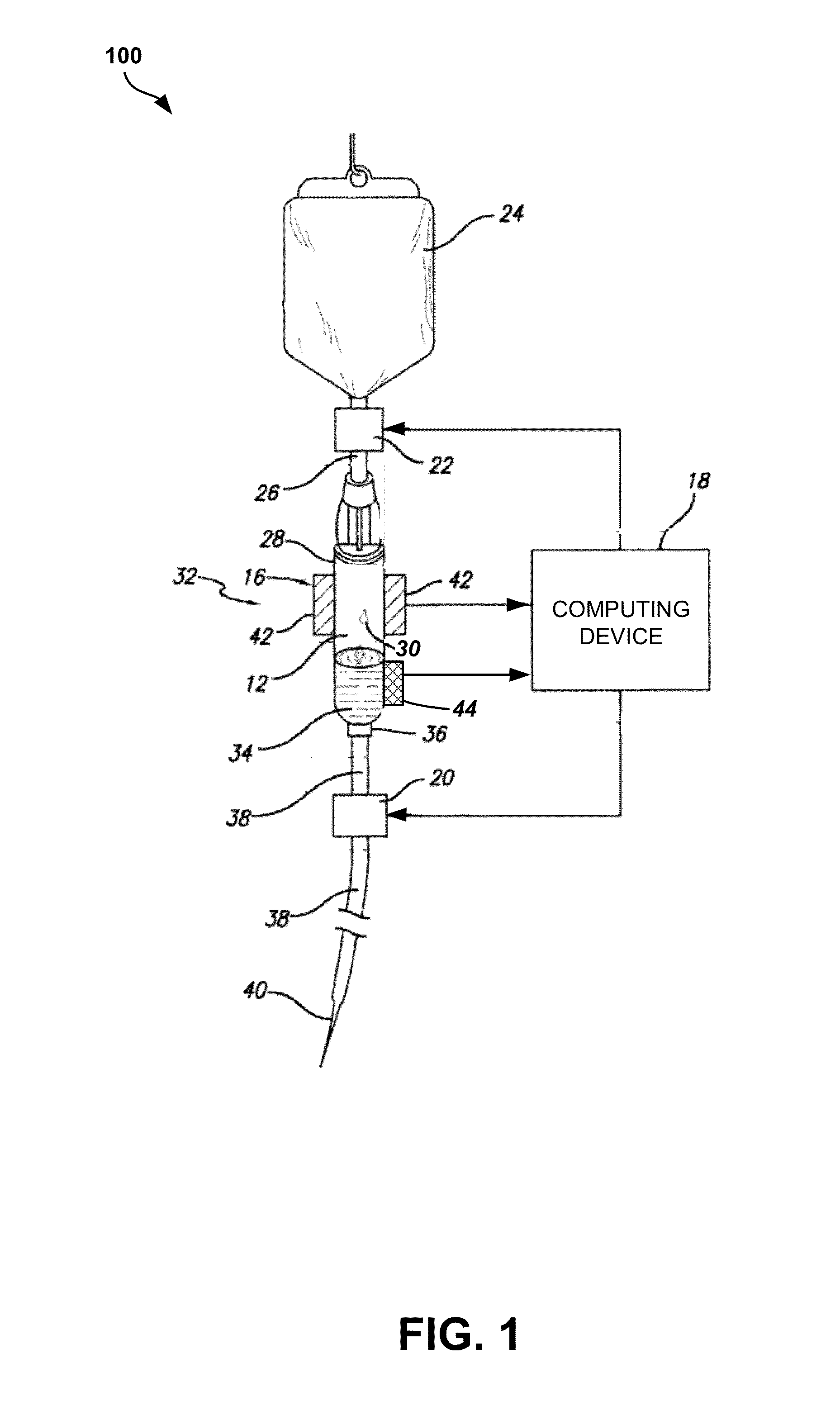
[0028]FIG. 1 illustrates an example of a fluid delivery system 100 that can be used in conjunction with an intravenous flow rate controller system constructed in accordance with the present disclosure. It will be appreciated that IV administration sets are well-known in the medical field and that the system 100 described herein is merely intended to be exemplary. As depicted, system 100 includes a container 24. Container 24 can be a bottle, a flexible IV solution container, or any other type of reservoir suitable for containing an IV solution. Container 24 is constructed such that an IV solution contained therein can be accessed for delivery to a patient. For example, container 24 can include an outlet port 22 having a pierceable closure. The pierceable closure is constructed of a material that allows it to receive a spike ther...


PUM


Abstract

Tilting of a drip chamber from its vertical axis during fluid administration can have negative effects upon the accuracy of systems configured for drop counting and/or for volumetric measurement of individual drops passing through the drip chamber. To address these negative effects, in accordance with one embodiment of the present disclosure, a fluid delivery system that measures the flow volume of a fluid delivery system is disclosed, which includes an imaging apparatus that captures a first image of a drip chamber while a drop is falling therein and a second image of the drip chamber with no drop. Portions of each image that are in substantially the same position in each image are subtracted.

Description

REFERENCE TO RELATED APPLICATION[0001]The present application claims priority to U.S. Provisional Patent Application No. 61 / 541,709, filed on Sep. 30, 2011, the entirety of which is hereby incorporated by reference.FIELD OF THE INVENTION[0002]The present disclosure relates generally to systems and methods for fluid delivery control, and more particularly, to intravenous (IV) medicament delivery systems and corresponding methods for flow-rate control and measurement.BACKGROUND OF THE INVENTION[0003]Intravenous (hereafter “IV”) infusion apparatuses are used to deliver a variety of IV solutions to a patient. The IV solution to be delivered to the patient is typically contained in a bottle or flexible container that is fluidly connected to a fluid administration set. The fluid administration set includes a length of tubing designed to run from the bottle or flexible container to a cannula configured for insertion into the patient's blood vessel. Various fluid control devices such as cla...

Claims


Application Information

Patent Timeline
IPC IPC(8): H04N7/18G16H20/17
CPCG05D7/0635G01F3/00A61M5/1411A61M5/1689G06F19/3468G01F1/72G01F22/00G06T7/602G06T2207/20224G01F1/56A61M2205/215G06T7/62G16H20/17
Inventor LOWERY, MICHAEL G.MARKEY, BRIAN G.MARKEY, JAMES A.
Owner ICU MEDICAL INC
Why Eureka
Try Eureka