Aircraft outflow valve

a technology of airflow valve and airbag, which is applied in the field of valves, can solve the problems of increasing cabin humidity, increasing cabin temperature, and increasing the concentration of undesired gasses, and achieve the effect of reducing airflow

Active Publication Date: 2013-04-04
THE BOEING CO
View PDF22 Cites 4 Cited by
  • Summary
  • Abstract
  • Description
  • Claims
  • Application Information

AI Technical Summary

Benefits of technology

[0006]In yet another aspect, a method of exhausting air from an aircraft is described. The method includes pivotally opening a gate coupled to a frame of an outflow valve from a closed position substantially parallel with an external surface of an aircraft to an exhaust position defining an angle to the external surface of the aircraft greater than zero to permit airflow from an interior of the aircraft to an exterior of the aircraft between the frame and a rear edge of the gate. The method includes maintaining a substantially constant gap between a forward edge of the gate and a flange extending from the frame toward an interior of the aircraft to substantially minimize airflow into the interior of the aircraft between the forward edge of the gate and the frame.

Problems solved by technology

Failures interrupting the supply of pressurized air from these air pressure sources may result in increased cabin temperatures, increased cabin humidity, an increased concentration of undesired gasses (such as carbon dioxide), and / or an increased likelihood of overheating equipment.
However, alternate air supply systems generally increase the cost, weight, and complexity of an aircraft.

Method used


Image

  • Aircraft outflow valve
  • Aircraft outflow valve
  • Aircraft outflow valve

Examples


Embodiment Construction

[0017]As used herein, an element or step recited in the singular and proceeded with the word “a” or “an” should be understood as not excluding plural elements or steps unless such exclusion is explicitly recited. Furthermore, references to “one embodiment” of the present invention or the “exemplary embodiment” are not intended to be interpreted as excluding the existence of additional embodiments that also incorporate the recited features.

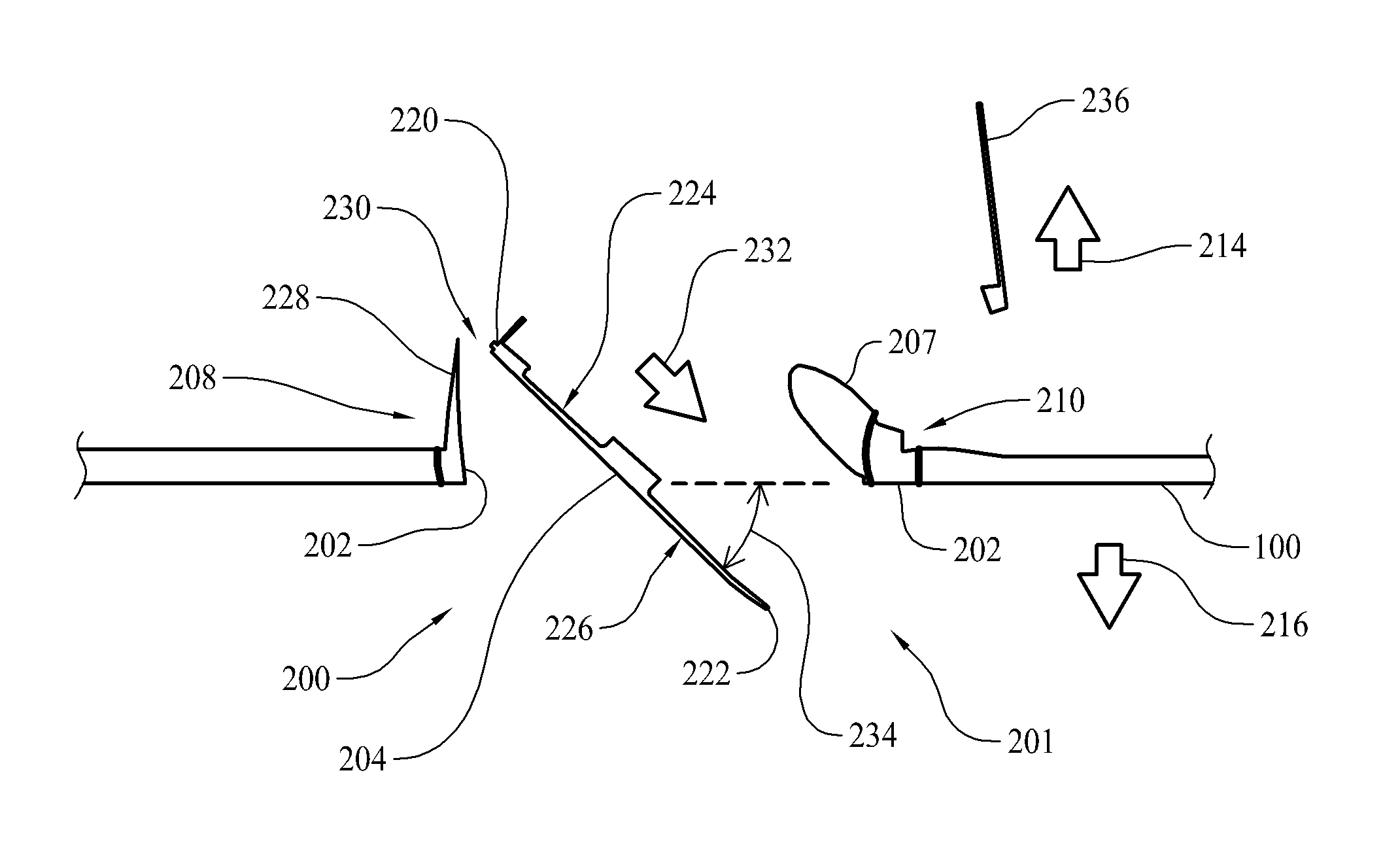
[0018]Exemplary outflow valves are described herein. The exemplary outflow valves described herein provide greater net airflow than some known outflow valves. Moreover, the exemplary outflow valves limit the amount of air that flows through the valve opposite to a direction that is the desired direction of flow, and thus provide a greater net airflow at each valve. The increased airflow may provide sufficient airflow for ventilation and cooling in an aircraft during a loss of inflow condition such that a separate backup system is not needed. As suc...


PUM


Abstract

Outflow valves for use in an aircraft are described. In one example, an outflow valve for use in an aircraft includes a frame configured for coupling to an aircraft and a gate pivotally coupled to said frame. The frame includes a forward flange extending above the frame. The gate is pivotally moveable between a closed position to substantially block airflow between an interior of the aircraft and an exterior of the aircraft and an exhaust position to direct airflow from the interior toward the exterior of the aircraft. The forward edge of the gate is located adjacent the frame forward flange as the gate is pivoted between the closed position to the exhaust position.

Description

BACKGROUND[0001]The field of the disclosure relates generally to valves, and more specifically to outflow valves for use in an aircraft.[0002]In aircraft pressurizing and ventilating systems, an air pressure source is typically provided to supply pressurized air to the cabin. Air pressure within the cabin is maintained at the required pressure by controlling the flow of air from the cabin through one or more outflow valves positioned in an opening or openings defined in the body of the aircraft. Air provided by the air pressure source is sometimes also used to cool various electronic devices within the aircraft.[0003]Failures interrupting the supply of pressurized air from these air pressure sources may result in increased cabin temperatures, increased cabin humidity, an increased concentration of undesired gasses (such as carbon dioxide), and / or an increased likelihood of overheating equipment. Consequently, at least some aircraft include an alternate air supply device for use in v...

Claims


Application Information

Patent Timeline
Patent Type & Authority Applications(United States)
IPC IPC(8): B64D13/00F16K3/30
CPCB64D13/02
Inventor AL-ALUSI, THAMIR R.SEDGWICK, LEIGH M.FOSTER, COYNE
Owner THE BOEING CO
Why Eureka
Try Eureka