
Building pressure control

a technology for building pressure and control, applied in ventilation systems, lighting and heating apparatus, heating types, etc., can solve the problems of poor efficiency, slow or stop of fans, etc., and achieve the effect of dramatically improving the performance of control strategies for multi-story facilities

Pending Publication Date: 2019-03-21
PATHIAN INC
View PDF4 Cites 12 Cited by
  • Summary
  • Abstract
  • Description
  • Claims
  • Application Information

AI Technical Summary

Benefits of technology

The patent text describes a method for controlling the performance of control strategies for multi-story facilities by accounting for stack effect pressurization. This method reduces the setpoint for the return fan, which results in a significant reduction in brake horsepower consumed by the air handler return air fan at all operating loads. The reduction in return air fan pressure also reduces the likelihood of wasteful scenarios, such as can occur when air flow is forced through the supply fan, causing the supply air fan to slow or stop, with the inefficient net result that supply air flow is generated from the return air fan driving air through the supply fan, which is far less efficient than using the supply air fan itself to provide supply air flow. The patent also describes a method for controlling the pressurization of a patient room in a healthcare environment to minimize airflows between rooms, which improves infection control by ensuring that patient rooms are supplied with filtered, relatively sterile air rather than receiving air from adjacent rooms which may bear infected patients.

Problems solved by technology

The major flaw in this control sequence is that it assumes the building is under a relative constant pressure differential vs. outside air, which is often not the case.
Furthermore, the reduction in return air fan pressure reduces the likelihood of wasteful scenarios, such as can occur when air flow is forced through the supply air fan by the high relative pressure, causing the supply air fan to slow or stop, with the inefficient net result that supply air flow is generated from the return air fan driving air through the supply fan, which is far less efficient than using the supply air fan itself to provide supply air flow.

Method used


Image

  • Building pressure control
  • Building pressure control
  • Building pressure control

Examples


Embodiment Construction

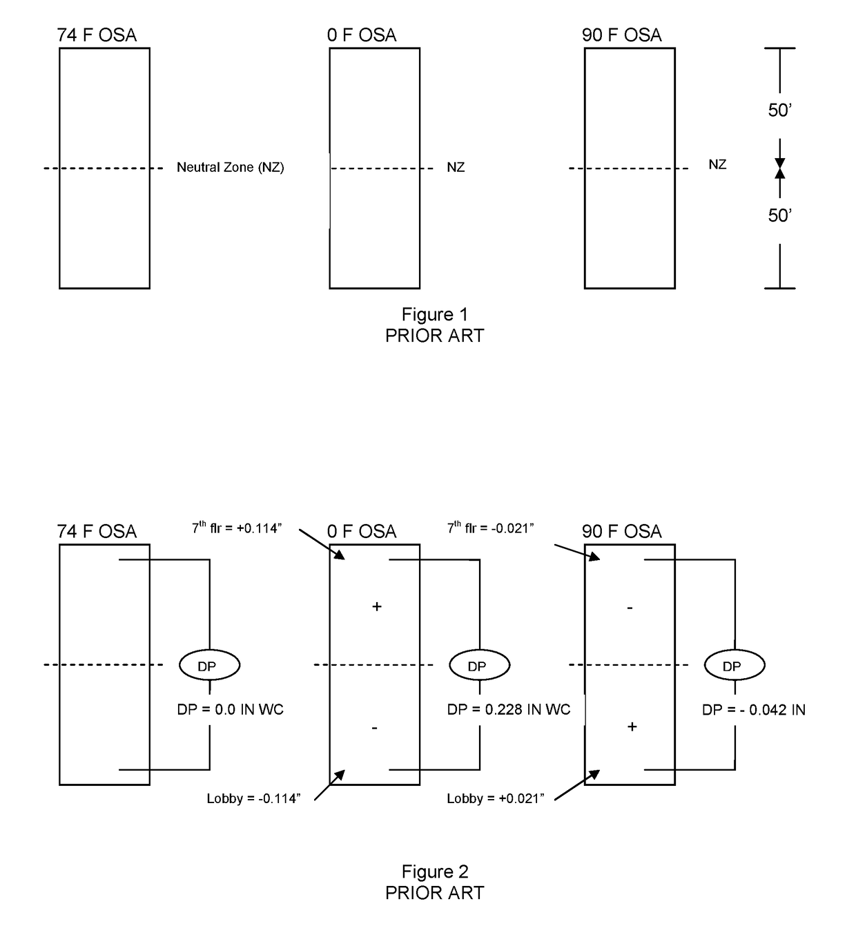
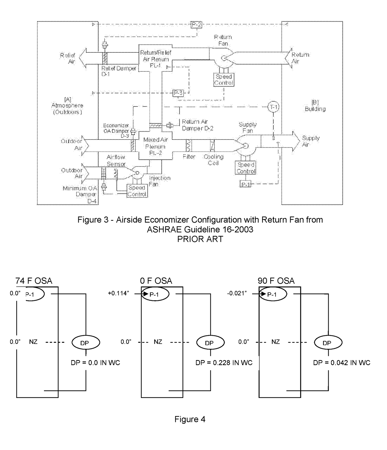
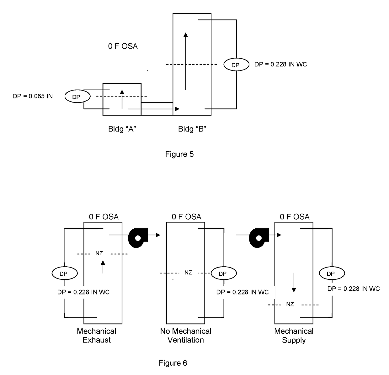
[0045]The inventor has shown that as the outside air temperature drops below 25 F, a relatively tall building's stack effect forces begin to overwhelm the ability of a conventional control sequence to maintain targeted building pressures, as pressure gradients resulting from stack effect cause large quantities of air migrate to the upper floors of the building. The increased pressure in the building's upper floors causes the upper floor air handlers to open the air handler relief air dampers to relieve that building pressure, tending to increase the air flows upward through the building and infiltration in the lower part of the building. The faster migrating air is exhausted from the lower part of the building to the upper part of the building, the faster the air rises in the building and the faster upper floor air handlers exhaust it. As a result, the building is turned into an induced draft chimney with unnecessary heat energy as well as mechanical energy ultimately being expended...


PUM


Abstract

The air flow of an HVAC system for a multi-story building B is controlled by optimizing the pressure setpoint at the return air plenum PL-1 used for removing or recirculate air from the building, by measuring a pressure differential between the building B air and atmosphere A air at a sensor location P-2, computing a desired pressure differential between the building B air and atmosphere A air, based upon a computed stack effect pressure that is expected to develop at the sensor location on the building for the current inside and outside air temperature in the absence of mechanical action, and controlling the return air fan and damper D-1 to pressurize the air in at the sensor location to produce the desired pressure differential between the building B air and atmosphere A air at the sensor P-2 location. Air pressure is also controlled between specific rooms and adjacent rooms by control of the conditioned air or return air paths connected thereto.

Description

RELATED APPLICATIONS[0001]The present invention is a continuations-in-part of U.S. Ser. No. 15 / 342,412 filed Nov. 3, 2016, which is a divisional of U.S. Ser. No. 13 / 890,940 filed May 9, 2013, both of which are incorporated herein in their entirety.FIELD OF THE INVENTION[0002]The present invention relates to the control of heating, ventilation and air conditioning (HVAC) systems in multi-story buildings.BACKGROUND OF THE INVENTION[0003]HVAC systems come in a variety of types, each with specific characteristics and operational constraints. The components include air handlers and HVAC control systems. Air handlers input output and return fans, and may include Variable Frequency Drives (VFD's). The system may use exhaust, return, and outside air damper(s) which can be opened or closed or placed in intermediate positions in response to variable conditions. Control systems may include air differential pressure transmitters, minimum outside air flow transmitters and other devices to implem...

Claims


Application Information

Patent Timeline
IPC IPC(8): F24F11/72F24F7/08F24F11/74
CPCF24F2221/50F24F7/08F24F11/74F24F11/72F24F11/0001F24F2011/0004F24F2110/40
Inventor BUCHANAN, DANIEL
Owner PATHIAN INC
Learn More