
Optical connector assembly comprising a shutter

a technology of optical connectors and shutters, applied in optics, instruments, optical light guides, etc., can solve problems such as more complex, and achieve the effects of reducing airflow, preventing physical damage of optical interfaces, and effectively protecting against contamination

Active Publication Date: 2021-12-07
HUBERSUHNER AG
View PDF37 Cites 0 Cited by
  • Summary
  • Abstract
  • Description
  • Claims
  • Application Information

AI Technical Summary

Benefits of technology

The patent describes a shutter assembly that can protect optical connectors and interfaces from contamination and damage. The shutter is designed to minimize airflow and prevent dust transport during connection and disconnection. It can also be designed for high packing density and cost efficiency. The shutter offers a self-closing mechanism and can be designed with low connection force. It can also be designed to protect against electromagnetic fields and can be used for transmission of electrical signals and control indication. The shutter design supports high packing density and is robust and cost efficient. A sealing means can be arranged to seal the ferrules with respect to the environment.

Problems solved by technology

The connector assemblies comprising a shutter as known from the prior art have a complex design, are difficult to operate and normally require a male and a female part which makes it even more complex.

Method used


Image

  • Optical connector assembly comprising a shutter
  • Optical connector assembly comprising a shutter
  • Optical connector assembly comprising a shutter

Examples


Embodiment Construction

[0028]Reference will now be made in detail to certain embodiments, examples of which are illustrated in the accompanying drawings, in which some, but not all features are shown. Indeed, embodiments disclosed herein may be embodied in many different forms and should not be construed as limited to the embodiments set forth herein; rather, these embodiments are provided so that this disclosure will satisfy applicable legal requirements. Whenever possible, like reference numbers will be used to refer to like components or parts.

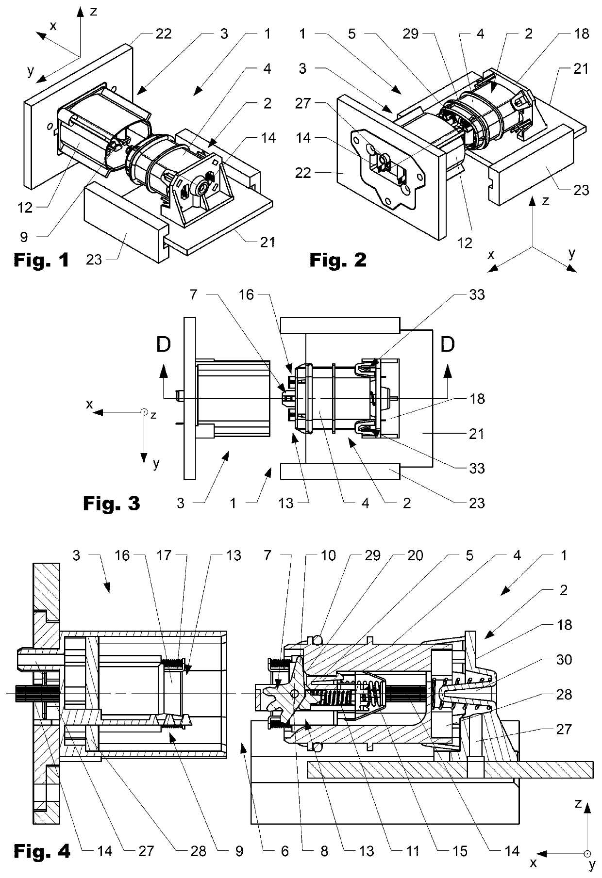
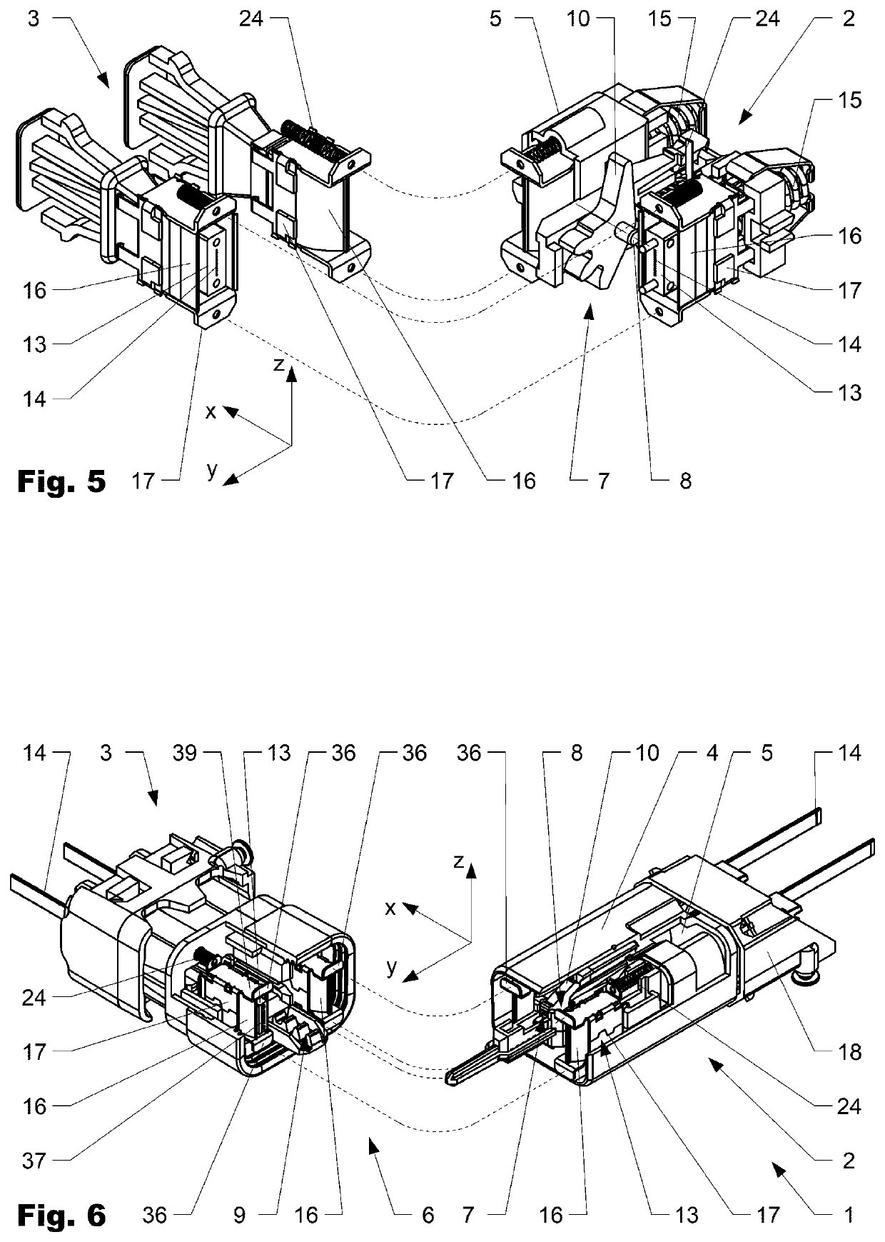
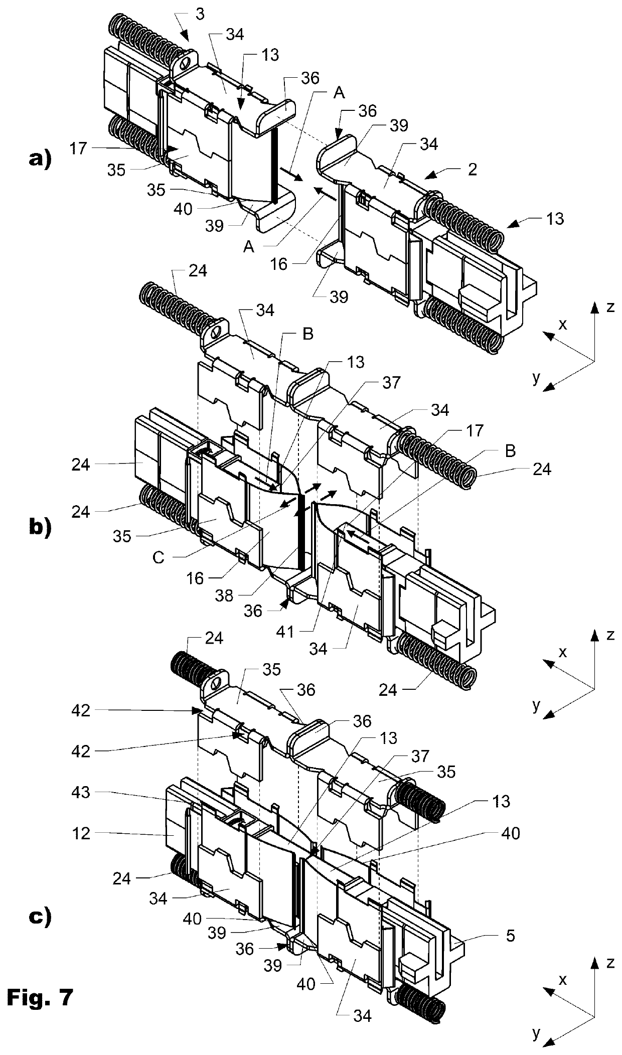
[0029]FIG. 1 shows a connector assembly 1 in a perspective view from above and right in an uncoupled manner. FIG. 2 show the connector assembly 1 in a perspective view from above and left. FIG. 3 shows the connector assembly 1 in a top view. FIG. 4 shows the connector assembly 1 in a section view along section line DD of FIG. 3. FIG. 5 shows 2×2 ferrules 13 normally arranged inside and forming part of a variation of the connector assembly 1. FIG. 6 shows a second...


PUM


Abstract

The invention is directed to a connector assembly (1) comprising a first connector part (2) which is interconnectable to a second connector part (3). The first connector part (2) comprises a ferrule (13) which is encompassed by a shutter frame (17) and a thereto attached shutter (16). The shutter (16) is arranged movable with respect to the ferrule (13) in a first direction (x) between a closed position, in which the shutter (16) encompasses a connection face (37) of the ferrule (13), and an open position, in which the connection face (37) is set free from the shutter (16). The shutter frame (17) and / or the shutter (16) comprises at least one locating surface (36) which during mating interacts with the second connector part (3) such that the shutter (16) is displaced relative to the ferrule (13) from the closed to the open position.

Description

BACKGROUND OF THE INVENTIONField of the Invention[0001]The present invention relates to a connector assembly comprising a shutter to prevent pollution, especially during interconnection of a first and a second connector part.Discussion of Related Art[0002]US 2014219624 A was first published in 2014 in the name of Xyratex Tech Ltd. and is directed to an optical connector for coupling with a complementary optical connector and for supporting an optical component. The connector comprises a cover moveable between a first and second position. The cover may also comprise a moveable shield and biasing components. Furthermore an optical connector assembly comprising covers that sequentially open is provided.[0003]US 2013315539 A was first published in 2013 in the name of Japan Aviation Electron. It provides an optical connector whose miniaturization is easier than conventional. The optical connector comprises a housing holding an optical member, a slider slidably held by the housing, a shut...

Claims


Application Information

Patent Timeline
Patent Type & Authority Patents(United States)
IPC IPC(8): G02B6/38
CPCG02B6/3849G02B6/3821G02B6/3825G02B6/3893G02B6/3897G02B6/3816G02B6/3879G02B6/3885
Inventor TRAUSCHEIN, LIEBMERKOFFEL, PHILIPPTIBOLLA, DOMINIK
Owner HUBERSUHNER AG
Learn More