Electronically Controlled Valve System For Distributing Particulate Material

a technology of electronic control valve and particulate material, which is applied in the field of agricultural equipment, can solve problems such as system imbalance, and achieve the effects of equalizing back pressure, reducing back pressure, and reducing back pressur

Pending Publication Date: 2021-09-30
CNH IND AMERICA LLC
View PDF8 Cites 1 Cited by
  • Summary
  • Abstract
  • Description
  • Claims
  • Application Information

AI Technical Summary

Benefits of technology

[0005]The present invention provides an electronically controlled valve in each air distribution line for delivering product-conveying air to a boom section of an agricultural machine. The valves can be used to balance airflow between lines by controlling back pressure at the boom sections. In one aspect, an electronically controlled butterfly valve can be installed in each air line between a fan's plenum outlet and a dry product delivery meter. Each valve can be configured to allow some flow when in a closed position. This could be achieved, for example, by configuring a valve plate with a circular perimeter shape that has a smaller diameter than an inner diameter of the line or tube in which the valve plate is mounted. The circular valve plate can be concentrically centered in the air line and mounted on a shaft that is driven to pivot by an electric motor or other actuator. When in a fully closed position, the valve plate can extend perpendicular to a longitudinal axis of the line. This can present an entire surface area of the valve plate to resist airflow to the line, forcing the airflow through an annular gap between an outer edge of the circular valve plate and an inner circumferential surface of the air line, providing the greatest amount of back pressure against

Problems solved by technology

In any system where airflow is divided from one source to multiple destinations, there is the possibility of creating imbalance in the system in certain scenarios such as: going up or across a hill, shutting o

Method used


Image

  • Electronically Controlled Valve System For Distributing Particulate Material
  • Electronically Controlled Valve System For Distributing Particulate Material
  • Electronically Controlled Valve System For Distributing Particulate Material

Examples


Embodiment Construction

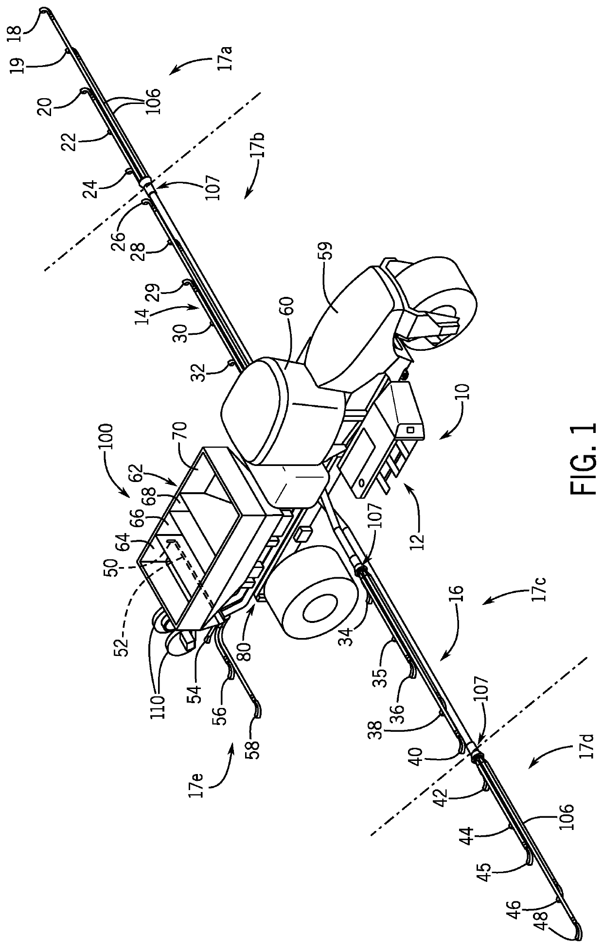
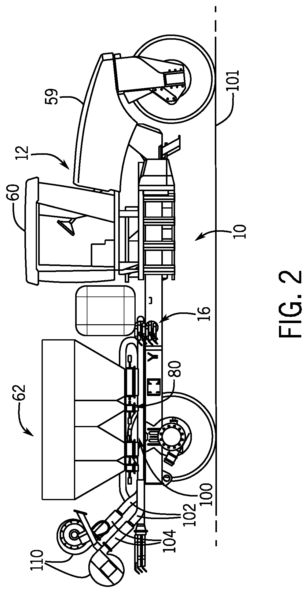
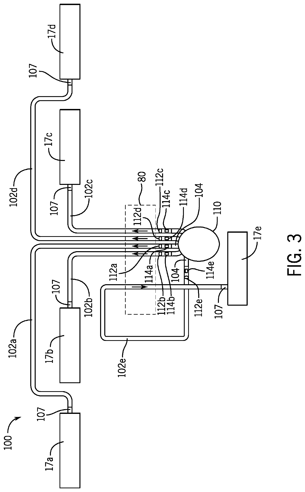
[0018]Referring now to the drawings, and more particularly to FIGS. 1 and 2, there is shown an agricultural application implement 10, which could be a dry pneumatic granular applicator. As is known in the art, implement 10 generally includes a large wheeled transport unit 12 such as truck or tractor, and laterally extending particle delivery booms 14 and 16, which may be pivoted to a stowed position close to the implement for storage or transport. Each boom 14, 16 extends laterally from the implement 10 in opposite directions. Each boom 14, 16 includes a plurality of boom sections 17, such as left outer and left inner boom sections 17a, 17b of boom 14, and right inner and right outer boom sections 17c, 17d of boom 16. Each boom section 17 is defined by a large diameter supply line 102 for supplying the boom section with granular or particulate material, such as seed, fertilizer, herbicide, insecticide and the like. Each boom section 17 includes a plurality of boom tubes or conduits ...


PUM


Abstract

The present invention provides an electronically controlled valve in each air distribution line for delivering product-conveying air to a boom section of an agricultural machine. The valves can be used to balance airflow between lines by controlling back pressure at the boom sections. In one aspect, an electronically controlled butterfly valve can be installed in each air line between a fan's plenum outlet and a dry product delivery meter. Each valve can be configured to allow some flow when in a closed position. This could be achieved, for example, by configuring a valve plate with a circular perimeter shape that has a smaller diameter than an inner diameter of the line or tube in which the valve plate is mounted.

Description

FIELD OF THE INVENTION[0001]The present invention pertains to agricultural equipment and, more specifically, to a system for distributing particulate material from an applicator in which valves in supply lines for entraining particulate material in airflow are configured to actuate between open and closed positions in which the open position maximizes airflow in the supply line by minimizing restriction of airflow presented by the valve and the closed position minimizes airflow in the supply line by maximizing restriction of airflow presented by the valve while still allowing a minimum airflow to pass.BACKGROUND OF THE INVENTION[0002]Agricultural product delivery systems are known to utilize various mechanisms, including mechanical and pneumatic systems to move granular or particulate material or product, such as fertilizer, seed, insecticide or herbicide, from a product supply chamber, through a series of elongated tubes that extend from a product supply chamber to a product applic...

Claims


Application Information

Patent Timeline
IPC IPC(8): A01M7/00F16K1/22
CPCA01M7/0089F16K31/041F16K1/22A01M7/005F16K1/222F16K2200/401A01M9/003A01M9/0092A01C15/04A01C7/081
Inventor RUPPERT, REXLINDEMEIER, RANDYMARTIN, JEFFREY SCOTAMUNDSON, JEREMY
Owner CNH IND AMERICA LLC
Why Eureka
Try Eureka