Magnetic Pulse Welding and Forming for Plates

a technology of magnetic pulse welding and plate, which is applied in the direction of non-electric welding apparatus, manufacturing tools, and capacitors, etc., can solve the problems of unusable or inefficient use, significant deformation of one or more plates, and undesirable cycle time for creating the shap

Active Publication Date: 2013-04-11
DANA AUTOMOTIVE SYST GRP LLC
View PDF6 Cites 28 Cited by
  • Summary
  • Abstract
  • Description
  • Claims
  • Application Information

AI Technical Summary

Problems solved by technology

Ultrasonic welding is well-known, readily available and cost-effective, however, it has disadvantages, particularly for battery plates.
Often ultrasonic welding of battery plates results in significant deformation of one or more of the plates at the weld location when the weld is completed.
This permanent deformation can damage or ruin the plates thus making them unusable or inefficient.
Presses and dies are frequently used but, depending on the desired shape, the cycle time to create the shape can be undesirable.
Additionally, it can be difficult to create some shapes using presses / dies.

Method used


Image

  • Magnetic Pulse Welding and Forming for Plates
  • Magnetic Pulse Welding and Forming for Plates
  • Magnetic Pulse Welding and Forming for Plates

Examples


Embodiment Construction

[0027]It is to be understood that the invention may assume various alternative orientations and step sequences, except where expressly specified to the contrary. It is also to be understood that the specific devices and processes illustrated in the attached drawings, and described in the following specification are simply exemplary embodiments of the inventive concepts defined herein. Hence, specific dimensions, directions or other physical characteristics relating to the embodiments disclosed are not to be considered as limiting, unless expressly stated otherwise.

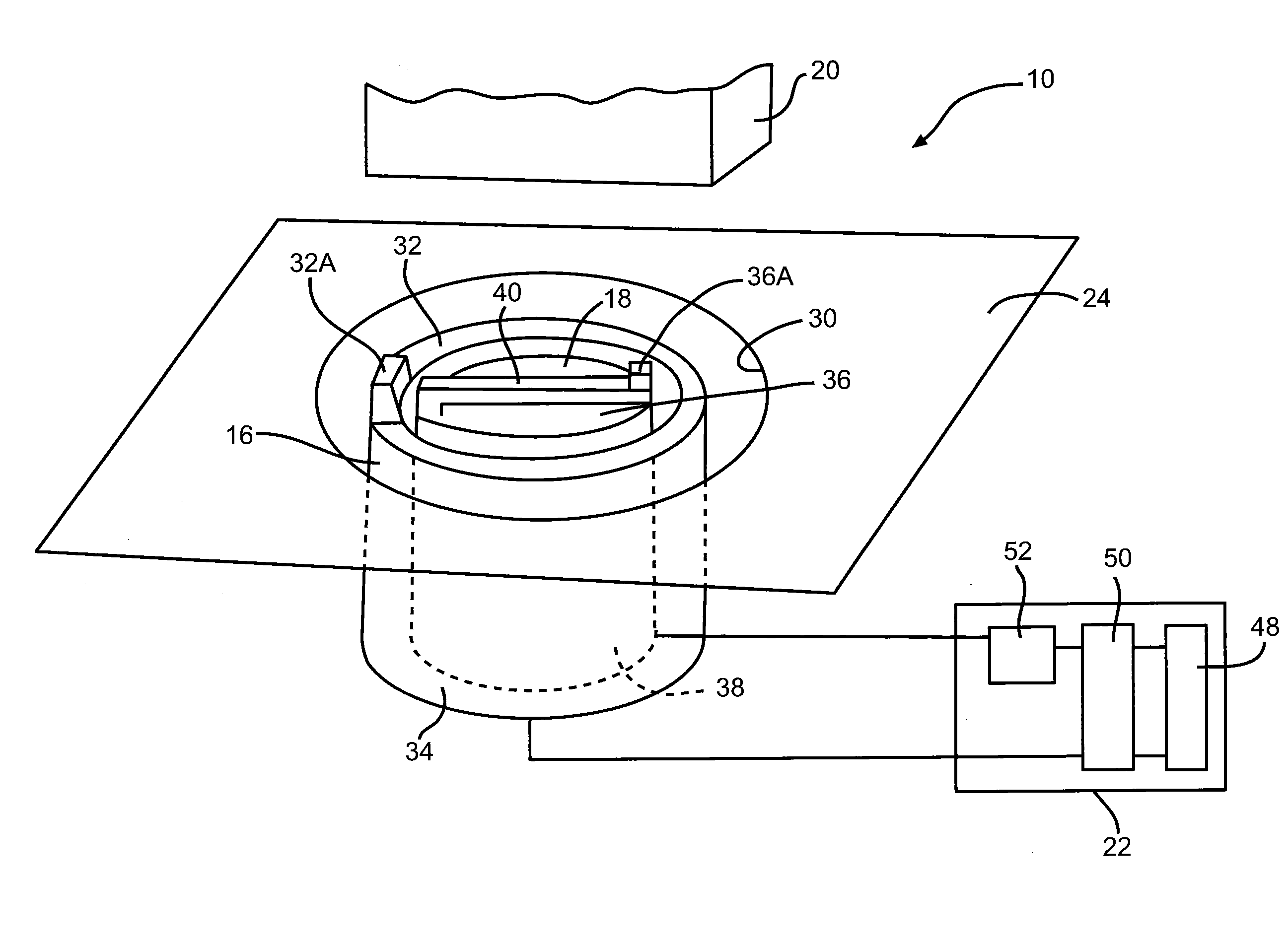
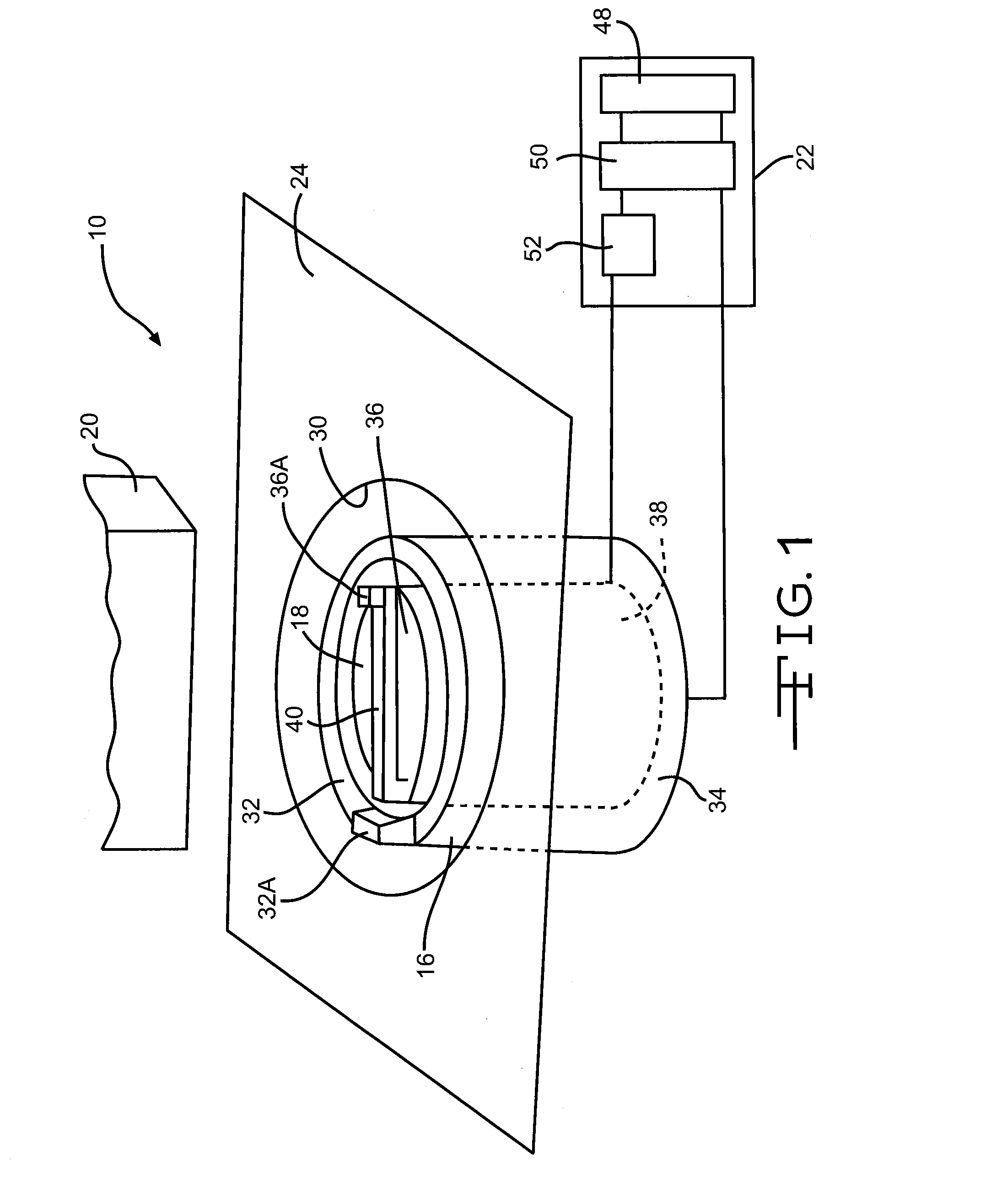
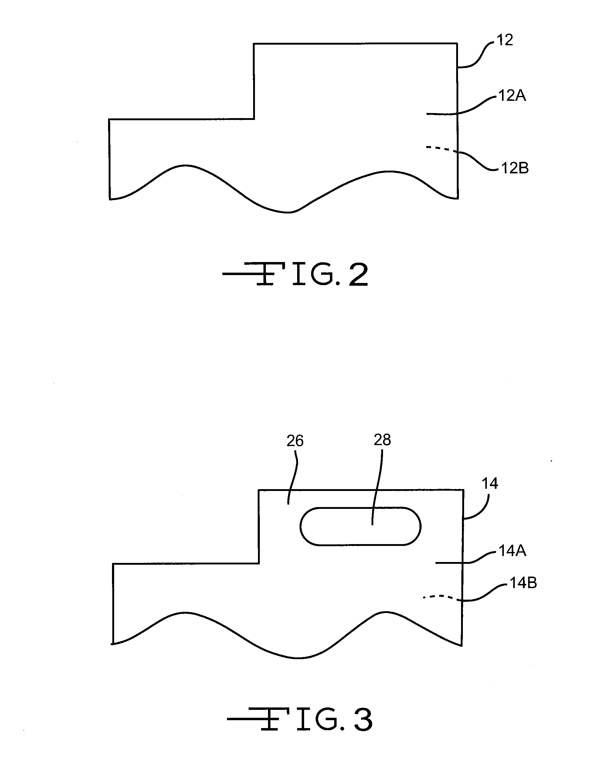
[0028]FIG. 1 illustrates a pulse welding system 10 for welding a first workpiece 12 (as shown in FIG. 2) to a second workpiece 14 (as shown in FIG. 2) according to one embodiment.

[0029]The pulse welding system 10 includes a first terminal 16, a proximity conductor 18, a restraining member 20, and a pulse circuit 22. As shown in FIG. 1, the first terminal 16 and the proximity conductor 18 can be mounted adjacent a work surf...


PUM

PropertyMeasurementUnit
angleaaaaaaaaaa
hemispherical shapeaaaaaaaaaa
insulatoraaaaaaaaaa

Abstract

A method of welding two workpieces together is described. A conductor in electrical communication with a pulse circuit is provided. A portion of the second workpiece is located adjacent the conductor. The two workpieces are also located together. A portion, or all, of one workpiece is welded to the other by applying a pulse current to one of the workpieces. A method of forming a workpiece is disclosed using a pulse current to move the workpiece into a desired shape.

Description

RELATED APPLICATIONS[0001]This application claims priority to U.S. patent application Ser. No. 61 / 545,324 filed on Oct. 10, 2011 which is incorporated by reference in its entirety.FIELD OF THE INVENTION[0002]The present invention relates to magnetic pulse welding and forming and more specifically to using magnetic pulse welding to couple plates, such as battery plates, or using magnetic pulse forming to form plates.BACKGROUND OF THE INVENTION[0003]There are a variety of methods for connecting plates together, such as plates for a battery. A common method of connecting the battery plates together is by welding. One type of welding that is used is ultrasonic welding. Ultrasonic welding is well-known, readily available and cost-effective, however, it has disadvantages, particularly for battery plates.[0004]Often ultrasonic welding of battery plates results in significant deformation of one or more of the plates at the weld location when the weld is completed. This permanent deformation...

Claims


Application Information

Patent Timeline
Patent Type & Authority Applications(United States)
IPC IPC(8): B23K13/01B21D26/14
CPCB23K20/06Y10T29/49803Y10S72/707B23K2201/38B23K2101/38
Inventor YABLOCHNIKOV, BORIS A.STEIGERWALT, EVE S.O'NEIL, TOMKUMMEROW, JACK A.
Owner DANA AUTOMOTIVE SYST GRP LLC
Why Eureka
Try Eureka