Spring brake

a spring and brake technology, applied in the field of springs, can solve problems such as unstable sunshade, and achieve the effect of stable spring for

Inactive Publication Date: 2013-04-11
NIEN MADE ENTERPRISE CO LTD
View PDF0 Cites 16 Cited by
  • Summary
  • Abstract
  • Description
  • Claims
  • Application Information

AI Technical Summary

Benefits of technology

[0006]The primary objective of the present invention is to provide a spring brake, which may provide the spring box a stable spring force.

Problems solved by technology

When the shade is totally unfolded and the mainspring is wound on the second reel, the shade is unstable because the recovery force of the mainspring will force the mainspring going back to the first reel.

Method used


Image

  • Spring brake
  • Spring brake
  • Spring brake

Examples


Embodiment Construction

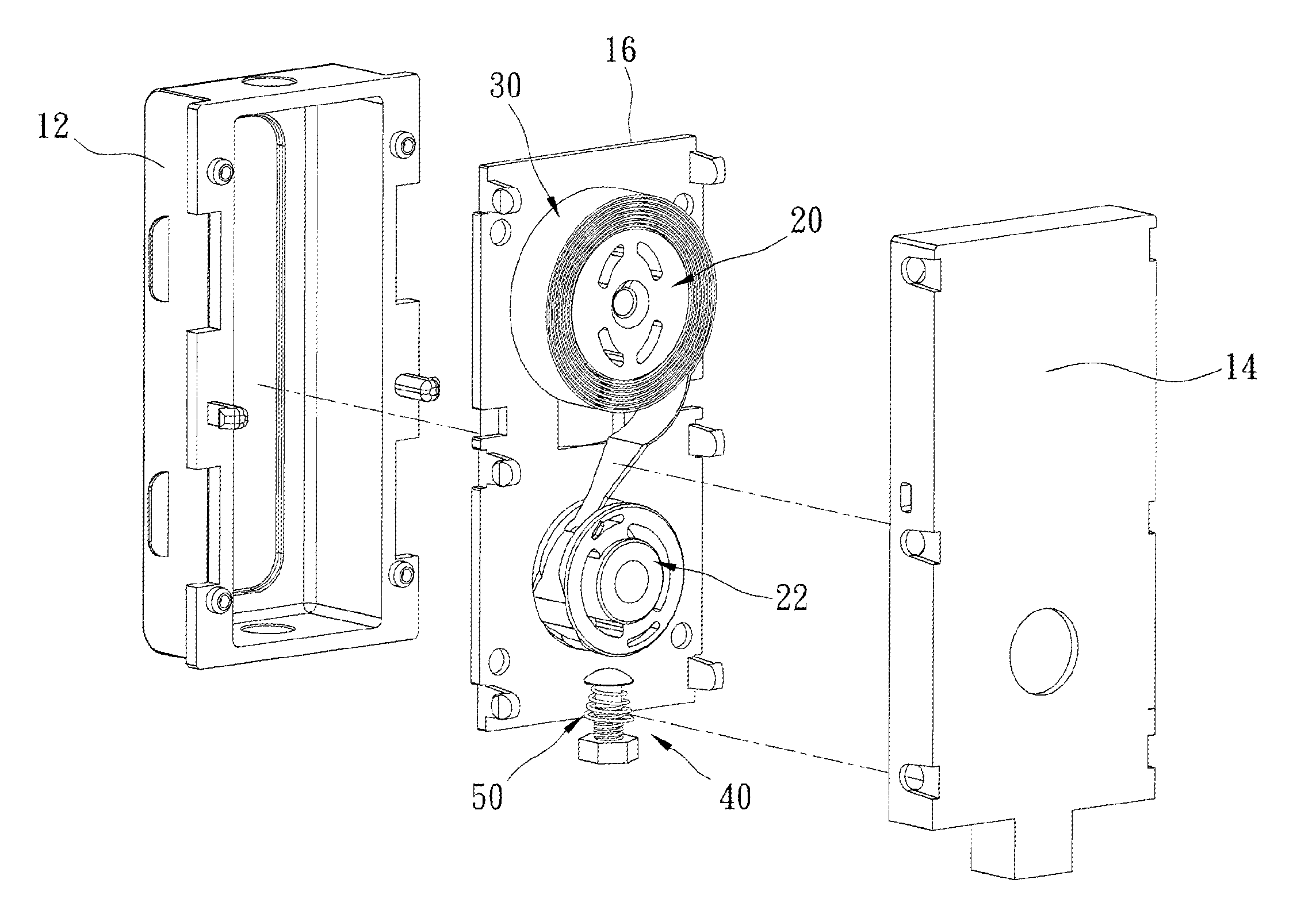
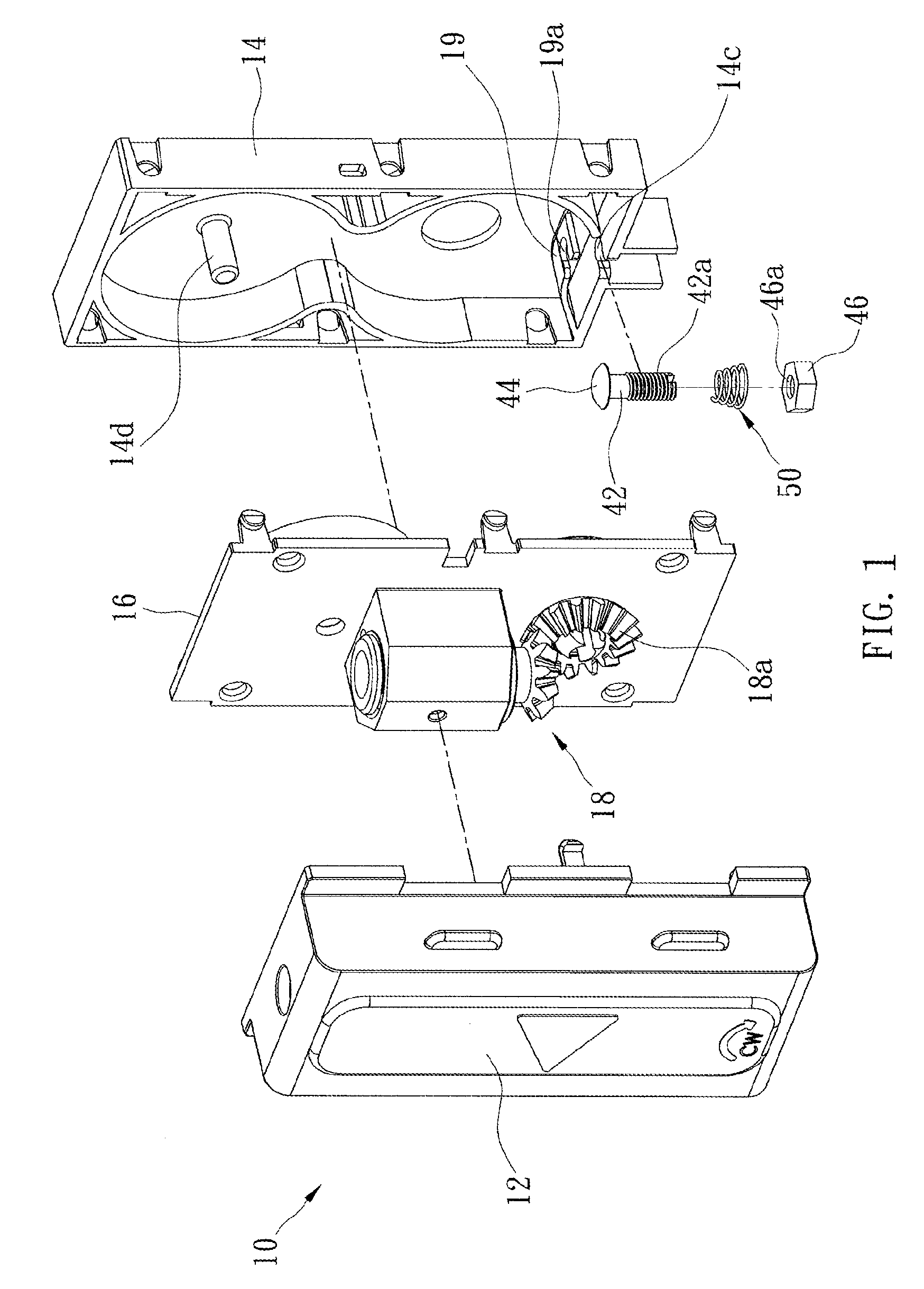
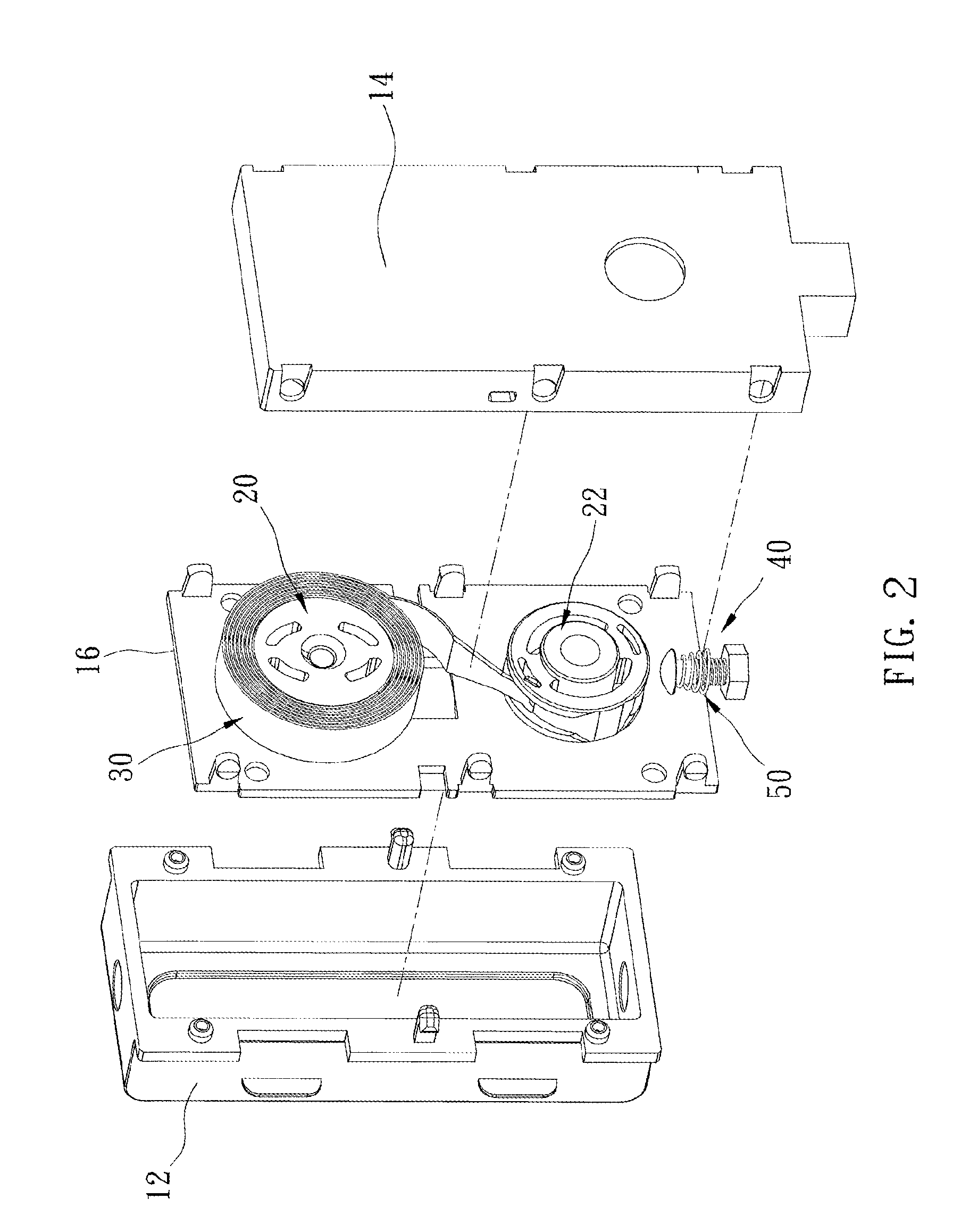
[0021]FIG. 1 and FIG. 2 show a spring brake of the first preferred embodiment of the present invention. The spring brake is received in a box 10 and is connected to a barrel (not shown) for winding a wire (not shown). The barrel is a conventional device, so we do not describe its detail here.

[0022]The box 10 includes a lid 12, a base 14, and a board 16. The base 14 is a part of the spring brake, in which two rooms 14a, 14b are provided. The board 16 is between the lid 12 and the base 14. A bevel gear set 18 is between the lid 12 and the board 16 to move the barrel. The base 14 has a bore 14c on a lateral wall, and the bore 14c extends to a top edge of the lateral wall. A rib board 19 is projected from an inner side of the base 14, and consequently the rib board 19 is flexible. The rib board 19 has a bore 19a corresponding to the bore 14a of the base 14. In the present embodiment, the bore 19a is open at a lateral edge of the rib board 19, and, however, it may be a closed bore.

[0023]...


PUM


Abstract

A spring brake includes a base, on which a first reel and a second reel are pivoted. A mainspring has opposite ends connected to the first reel and the second reel. A stop device has a pressing portion to press the mainspring when the mainspring is wound on the second reel. Therefore, the pressing portion of the stop device will touch the mainspring when the mainspring is wound on the second reel and give the mainspring a resistance to offset the recovery force of the mainspring.

Description

BACKGROUND OF THE INVENTION[0001]1. Field of the Invention[0002]The present invention relates generally to a spring, and more particularly to a spring brake.[0003]2. Description of the Related Art[0004]In a conventional window covering, it provides a spring box to receive cords, which connects to the slats, therein. U.S. patent application 2007 / 0261798 taught a cordless shade, in which a shaft is provided between a base and a spring box. The base has a barrel for the wire to be wound thereon. The spring box has a mainspring whose opposite ends respectively are fixed to a first reel and a second reel. The mainspring will be wound on the first reel when the shade is folded, and wound on the second reel when the shade is unfolded. The shaft has its opposite ends to connect to the barrel and a bevel gear to transmit a spring force of the mainspring and change the direction of the spring force to turn the barrel for winding the wire.[0005]When the shade is totally unfolded and the mainsp...

Claims


Application Information

Patent Timeline
Patent Type & Authority Applications(United States)
IPC IPC(8): F03G1/06
CPCE06B9/322
Inventor HSIEH, CHIA-CHING
Owner NIEN MADE ENTERPRISE CO LTD
Why Eureka
Try Eureka