Steering device

a steering device and steering shaft technology, applied in mechanical control devices, process and machine control, instruments, etc., can solve the problems of poor operation feeling and difficult operation of locking levers, and achieve the effects of improving retention force, good operation feeling and effective increase of pressure contact friction for

Active Publication Date: 2006-11-02
YAMADA SEISAKUSHO KK
View PDF3 Cites 19 Cited by
  • Summary
  • Abstract
  • Description
  • Claims
  • Application Information

AI Technical Summary

Benefits of technology

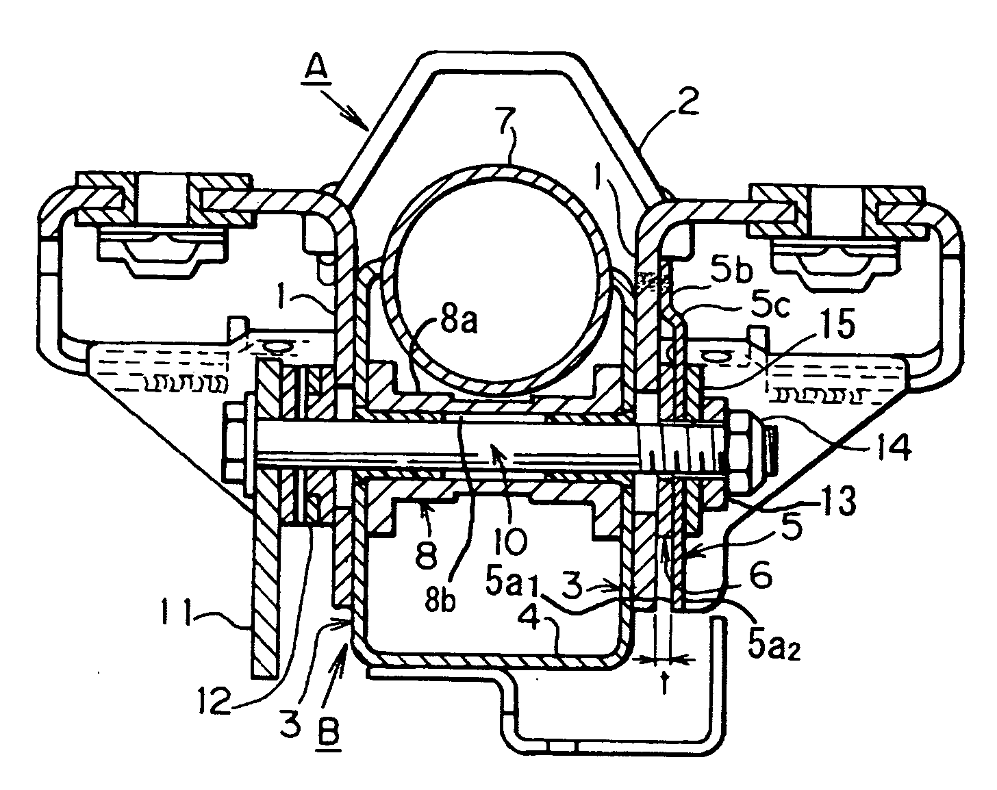
[0009] Also, plate thicknesses and materials differ, but between the column bracket 5 of the steering column 1 and the friction plate 12 the vertical part 7b of the body bracket 7 which is a separate member is sandwiched and held, so the return angle of the respective side surfaces can be different. Therefore, when the tilt lever 10 releases the locked state so that tilt movements can be made, deformation due to the return remains, so the surfaces that are in mutual confrontation with each other are in mutual contact with each other and press against each other, and as a result of the effect of the friction force a resistance to tilt movement occurs, and the operation feeling is poor. It is an object of the present invention to provide a sufficiently strong lock with a normal torque, in a very simple structure, and to provide very good operation feeling for the tilt movement with a very simple structure.
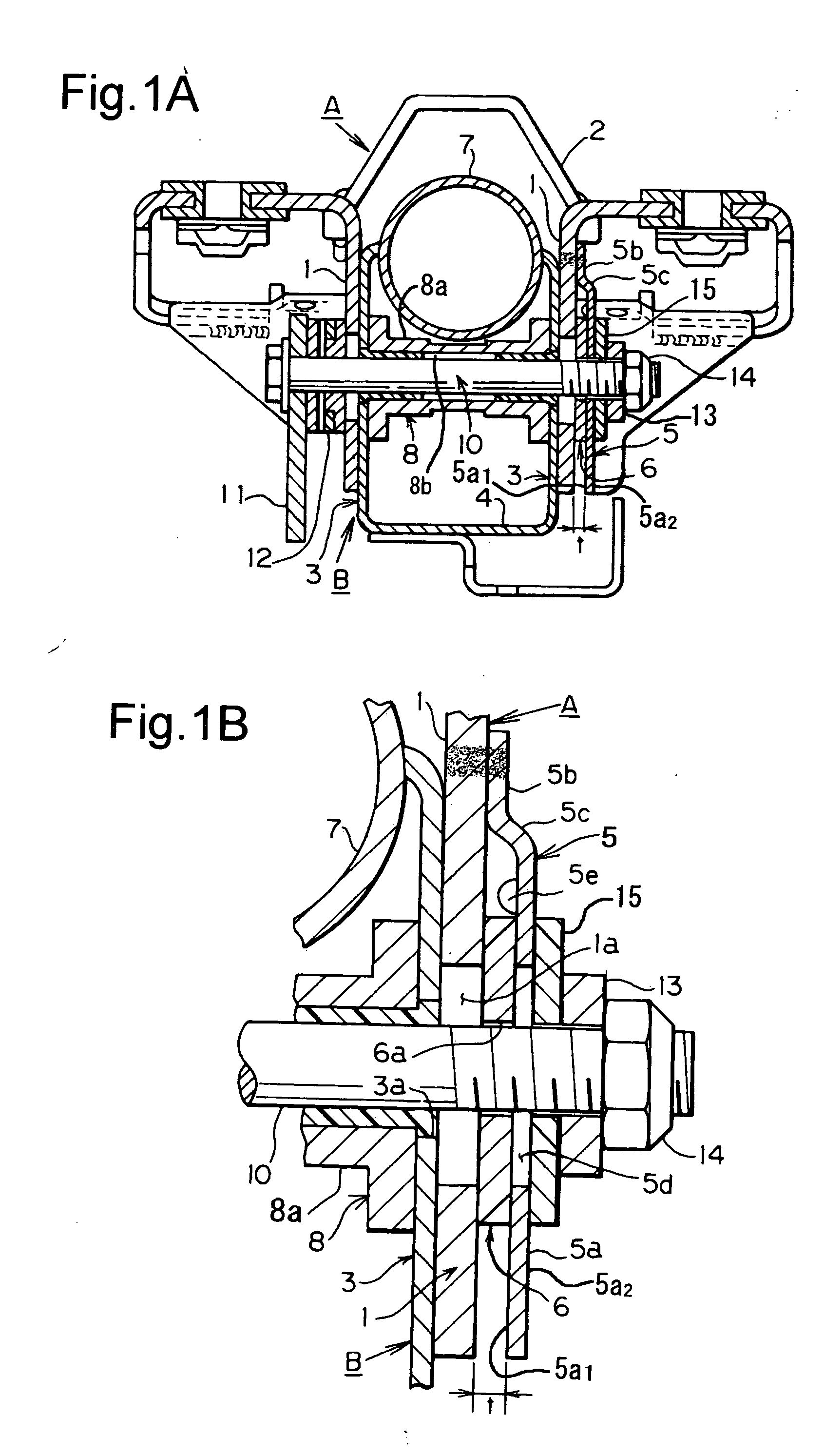
[0013] According to the invention of claim 1, by inserting the friction washer between the friction plate and the fixed side part of the fixed bracket, the friction plate is sandwiched. Therefore when these components are fastened by the lock bolt, the pressure contact friction force is effectively increased by the axial force of the lock bolt. Therefore the retention force can be improved. Also, when making tilt movements there is no contact or pressure between surfaces, so a good operation feeling is maintained. Also, by increasing the diameter of the friction washer still further, the retention forces can be stabilized.
[0014] According to the invention of claim 2, the part of the friction plate lower than the location where the friction plate is fixed separates elastically from the fixed side part when the lock of the lock bolt is released, so the friction plate and the friction washer do not contact each other with pressure. In this condition the movable bracket can move smoothly relative to the fixed bracket, particularly when making telescopic adjustments, so the adjustment feeling can be very good.
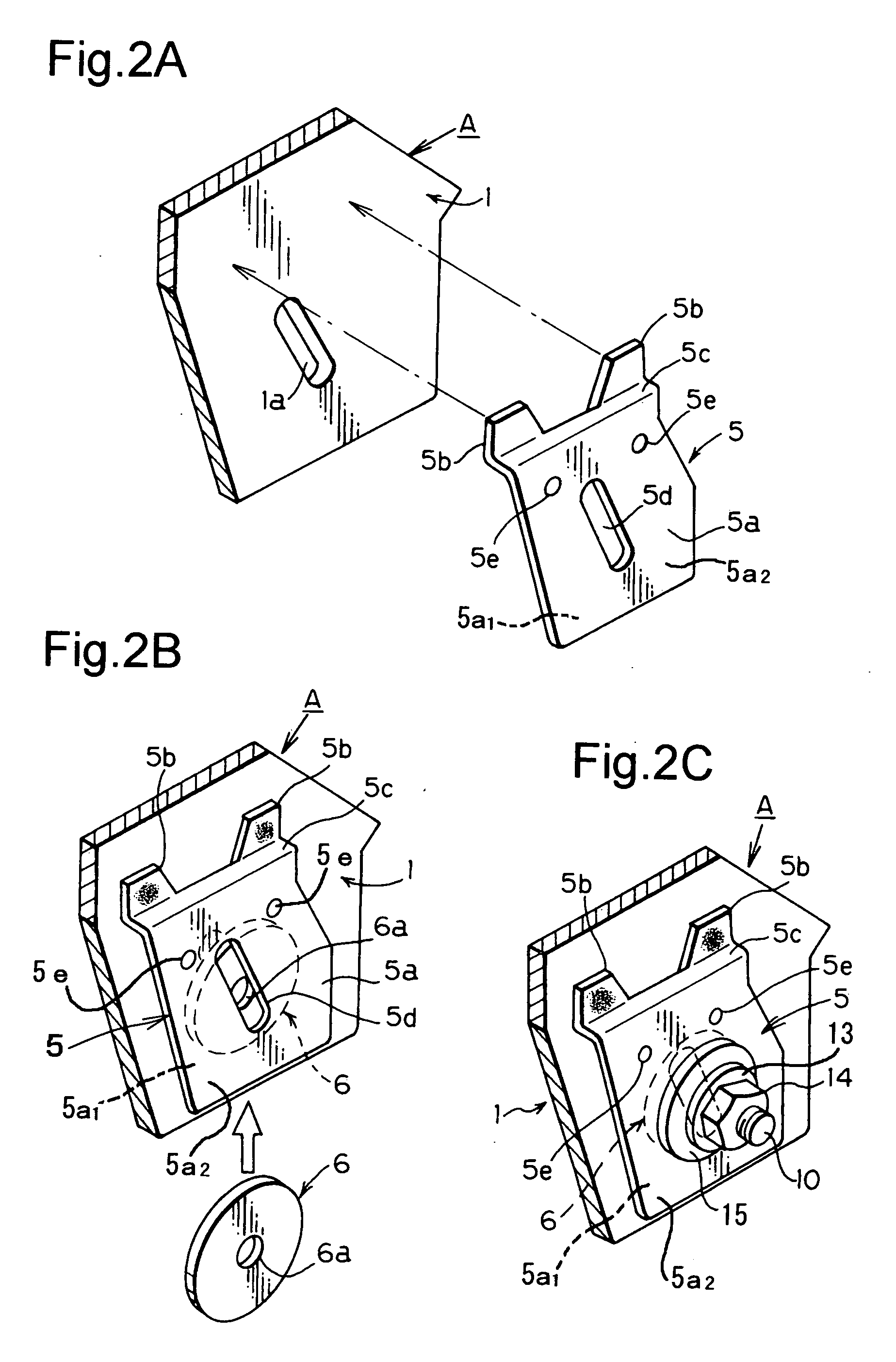
[0015] According to the invention of claim 3, the top edge of the friction plate is aligned with the upper part of the fixed side part and fixed. Therefore in assembly operations in the factory, the friction washer is inserted between the fixed side part and the friction plate from the lower part of the fixed bracket, so there is no obstruction to inserting the friction washer, insertion is made easier, and the operational efficiency can be improved. Next, according to the invention of claim 4, the plate thickness of the friction plate is thinner than the plate thickness of the fixed bracket, so there is good pressure contact between the friction plate and friction washer when locked by the lock bolt, so the fixing can be very strong.
[0016] According to the invention of claim 5, the friction plate and the friction washer are provided on both fixed side parts of the fixed bracket. Therefore, on both sides of the fixed bracket and the movable bracket in the width direction, the fastening force of the friction plate, friction washer, and lock bolt can act. Therefore an even stronger locked condition can be obtained. Also, according to the invention of claim 6, a collar member is provided between the two movable side parts of the movable bracket. Therefore the movable bracket is reinforced by the collar member in the width direction, so the movable bracket may be made from relatively thin metal, which contributes to weight reduction.
[0017] Next, according to the invention of claim 7, projections are provided to locate the friction washer in the correct position. Therefore the friction washer can be simply dropped between the friction plate and the fixed side part, and the friction washer will be positioned in the correct position in the gap between the friction plate and the fixed side part, so assembly operations can be efficiently carried out. According to the invention of claim 8, a washer is used together with the friction washer. Therefore, the fastening force on the plate shaped part can be made even stronger. Furthermore, the material and size of the washer and the friction washer can be made the same, so productivity can be improved, and therefore cost can be reduced.

Problems solved by technology

However, if too large a tightening torque is necessary the locking lever operation becomes difficult.
Therefore, when the tilt lever 10 releases the locked state so that tilt movements can be made, deformation due to the return remains, so the surfaces that are in mutual confrontation with each other are in mutual contact with each other and press against each other, and as a result of the effect of the friction force a resistance to tilt movement occurs, and the operation feeling is poor.

Method used


Image

  • Steering device
  • Steering device
  • Steering device

Examples


Embodiment Construction

[0028] The following is a description of the preferred embodiments of the present invention, based upon the drawings. First, as shown in FIGS. 1A, 3, and elsewhere, the configuration of the present invention includes mainly a fixed bracket A, a movable bracket B, a friction plate 5, a friction washer 6, and a lock bolt 10. The fixed bracket A includes a pair of fixed side parts 1, 1 that are oppositely arranged in the width direction, and an installation head part 2. The fixed side parts 1, 1 are substantially plate shaped, and the installation head part 2 is fixed to the top edges of the two fixed side parts 1 that are oppositely arranged.

[0029] Furthermore, as shown in FIGS. 2A, 3A and elsewhere, adjustment elongated holes 1a are formed in the fixed side parts 1. The adjustment elongated holes 1a are formed at a slant to the vertical direction. Also, if necessary the adjustment elongated holes are formed in a gradual circular arc shape in the elongated direction. The adjustment e...


PUM


Abstract

To provide a steering device for tilt and telescopic adjustments in which the locked condition can be made stronger, and when unlocked, tilt and telescopic adjustment can be smoothly carried out. A steering device, comprising: a fixed bracket having fixed side parts on both sides in the width direction; a movable bracket arranged between the fixed side parts; a friction plate fixed and oppositely arranged with a suitable gap with respect to at least one of the two fixed side parts of the fixed bracket; and a friction washer that is inserted between the fixed side part and the friction plate. A lock bolt passes through for connecting the fixed bracket, the movable bracket, the friction plate, and the friction washer to be freely locked and unlocked.

Description

BACKGROUND OF THE INVENTION [0001] 1. Field of the Invention [0002] The present invention relates to a steering device for tilt and telescoping adjustments, particularly to a steering device in which the locked state can be made stronger, and when carrying out tilt and telescopic adjustments in the unlocked state the operation can be made smoother. [0003] 2. Description of the Related Art [0004] Conventionally there are steering devices provided with a mechanism for tilt and telescopic adjustments. The common structure of this type of steering device includes a fixed bracket fixed to the vehicle body, and a movable bracket provided with a steering column. The movable bracket is fitted to the fixed bracket so that the movable bracket can pivot, move in the forward and backward directions, and be freely fixed. The movable bracket is normally sandwiched between the fixed bracket. [0005] Locking the fixed bracket and the movable bracket is carried out using a fastener such as a bolt and...

Claims


Application Information

Patent Timeline
Patent Type & Authority Applications(United States)
IPC IPC(8): G05G11/00G05G13/00
CPCY10T74/20256B62D1/184
Inventor OSAWA, TOSHIHITOIMAI, MASAYUKI
Owner YAMADA SEISAKUSHO KK
Why Eureka
Try Eureka