Floating type static spring seat and mechanical sealing structure thereof

A spring seat, static technology, applied in the direction of engine seals, mechanical equipment, engine components, etc., can solve the problems that affect the compensation of the end face of the mechanical seal by the spring, affect the function of spring compensation, and affect the use effect of the spring seat, etc. Simple, improved sealing performance, weight reduction effect

Inactive Publication Date: 2016-07-13
CHENGDU YITONG SEAL
View PDF8 Cites 2 Cited by
  • Summary
  • Abstract
  • Description
  • Claims
  • Application Information

AI Technical Summary

Problems solved by technology

The non-floating static spring seat is usually fixedly installed in the mechanical seal to support the spring. When in use, a push ring is set between the floating ring and the static spring seat, and the floating ring acts on the floating ring through the push ring. The structure is relatively complicated. ; At the same time, the processing direction of the spring hole on the existing non-floating static spring seat is the same as the fluid leakage direction, and the leaked fluid is easy to enter the spring hole, thereby affecting the compensation function of the spring
The rotary spring seat is a floating type. In actual use, the spring not only bears the friction between the contact surface with the spring seat, but also bears the gravity from the spring seat itself and the centrifugal force generated by the rotation, which is easy to twist the spring, especially When used in a multi-spring mechanical seal, the twisting and deformation of the spring is more serious, which affects the compensation of the spring to the end face of the mechanical seal; The section is longer, which in turn affects the floatability of the floating assembly and affects the actual use of the spring seat

Method used


Image

  • Floating type static spring seat and mechanical sealing structure thereof
  • Floating type static spring seat and mechanical sealing structure thereof
  • Floating type static spring seat and mechanical sealing structure thereof

Examples


Embodiment 1

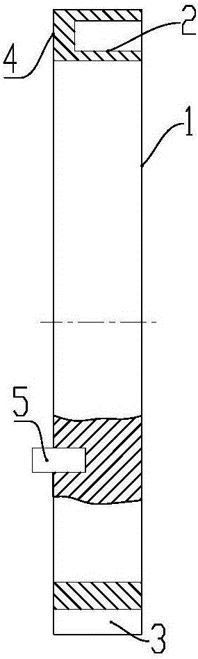
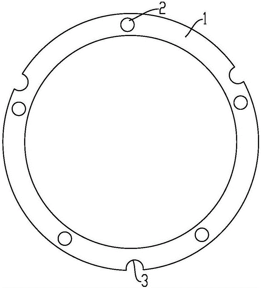
[0027] Such as figure 1 with 2 , a floating static spring seat, comprising an annular spring seat body 1, one end surface of the spring seat body 1 is an action surface 4 that interacts with a mechanical seal assembly, and the spring seat body 1 is connected to the action surface 4 A plurality of spring holes 2 are provided on the opposite end surface, and an anti-rotation structure that restricts the rotation of the spring seat is provided on the outside of the circumference of the spring seat body 1. The anti-rotation structure here is used to realize the sealing case of the spring seat and the mechanical seal. The connection between them is used to prevent the spring seat from rotating when the mechanical seal is working. The anti-rotation structure in this embodiment adopts at least one anti-rotation groove 3 outside the circumference of the spring seat body. Of course, other Similar structure, as long as there is no relative rotation between the spring seat and the seali...

Embodiment 2

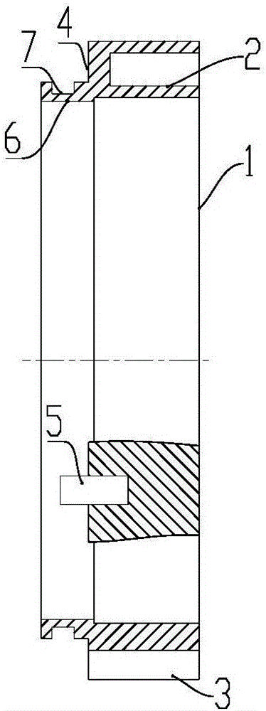
[0031] Such as image 3 As shown, a floating static spring seat includes an annular spring seat body 1, the end surface of one side of the spring seat body 1 is an active surface 4 that interacts with the mechanical seal assembly, and the spring seat body 1 is connected to the acting surface 4. A plurality of spring holes 2 are provided on the opposite end surface of the surface 4, and at least one anti-rotation groove 3 is provided on the outside of the circumference of the spring seat body 1; an outwardly extending support ring is provided on the active surface of the spring seat body 6. The support ring 6 is provided with an annular groove 7, and the support ring 6 and the spring seat body 1 are of an integral structure.

[0032] During installation, the supporting ring 6 of the spring seat extends into the static ring, and the outer peripheral surface of the supporting ring 6 cooperates with the inner peripheral surface of the static ring. There is good coaxiality between...


PUM


Abstract

The invention relates to the technical field of mechanical sealing, in particular to a floating type static spring seat which comprises an annular spring seat body, wherein the end surface on one side of the spring seat body is an acting surface acting on a sealing component; a plurality of spring holes are formed in the end surface of the other side, opposite to the acting surface, of the spring seat body; a rotation-preventing structure for limiting rotation of the spring seat is arranged on the outer side of the circumference of the spring seat body. The floating type static spring seat is simple in structure, the functions of a spring seat and a push ring are integrated, a spring can be effectively protected, the use property of the spring can be better brought into play, and a stable acting force can be provided for a sealed end surface in mechanical sealing. Besides, the invention further provides a mechanical sealing structure which can further improve the use property of the spring seat and is good in sealing effect.

Description

technical field [0001] The invention relates to the technical field of mechanical seals, in particular to a floating static spring seat and its mechanical seal structure. Background technique [0002] At present, the existing spring seats for mechanical seals usually adopt rotary spring seats that rotate together with the rotating components or non-floating stationary spring seats. The non-floating static spring seat is usually fixedly installed in the mechanical seal to support the spring. When in use, a push ring is set between the floating ring and the static spring seat, and the floating ring acts on the floating ring through the push ring. The structure is relatively complicated. At the same time, the processing direction of the spring hole on the existing non-floating static spring seat is the same as the fluid leakage direction, and the leaked fluid is easy to enter the spring hole, thereby affecting the compensation function of the spring. The rotary spring seat is ...

Claims


Application Information

Patent Timeline
IPC IPC(8): F16J15/34
CPCF16J15/3452F16J15/348
Inventor 曾军孙伟罗涛
Owner CHENGDU YITONG SEAL
Why Eureka
Try Eureka