Torque assembly and method of manufacture

a technology of torque assembly and manufacturing method, which is applied in the direction of manufacturing tools, wing accessories, instruments, etc., can solve the problems of reducing the resistance on the shaft to an undesirable amount, reducing the friction on the shaft, and other materials suffering from wear or deformation

Inactive Publication Date: 2013-04-25
VENTURESOURCE SOLUTIONS
View PDF3 Cites 31 Cited by
  • Summary
  • Abstract
  • Description
  • Claims
  • Application Information

AI Technical Summary

Problems solved by technology

Unfortunately, conventional torque hinges of all styles suffer from disadvantages in that they tend to wear out over time, decreasing the amount of friction on the shaft and thus reducing the amount of resistance on the shaft to an undesirable amount.
Other materials suffer from wear or deformation, which tends to reduce the friction between those materials and the shaft over time.
Many torque hinge designs are incapable of meeting current heightened safety and quality standards in various industries.

Method used


Image

  • Torque assembly and method of manufacture
  • Torque assembly and method of manufacture
  • Torque assembly and method of manufacture

Examples


Embodiment Construction

[0021]II. Overview

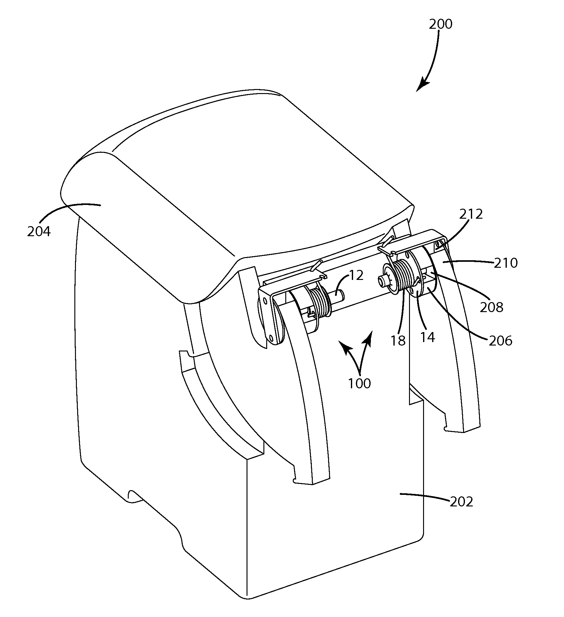
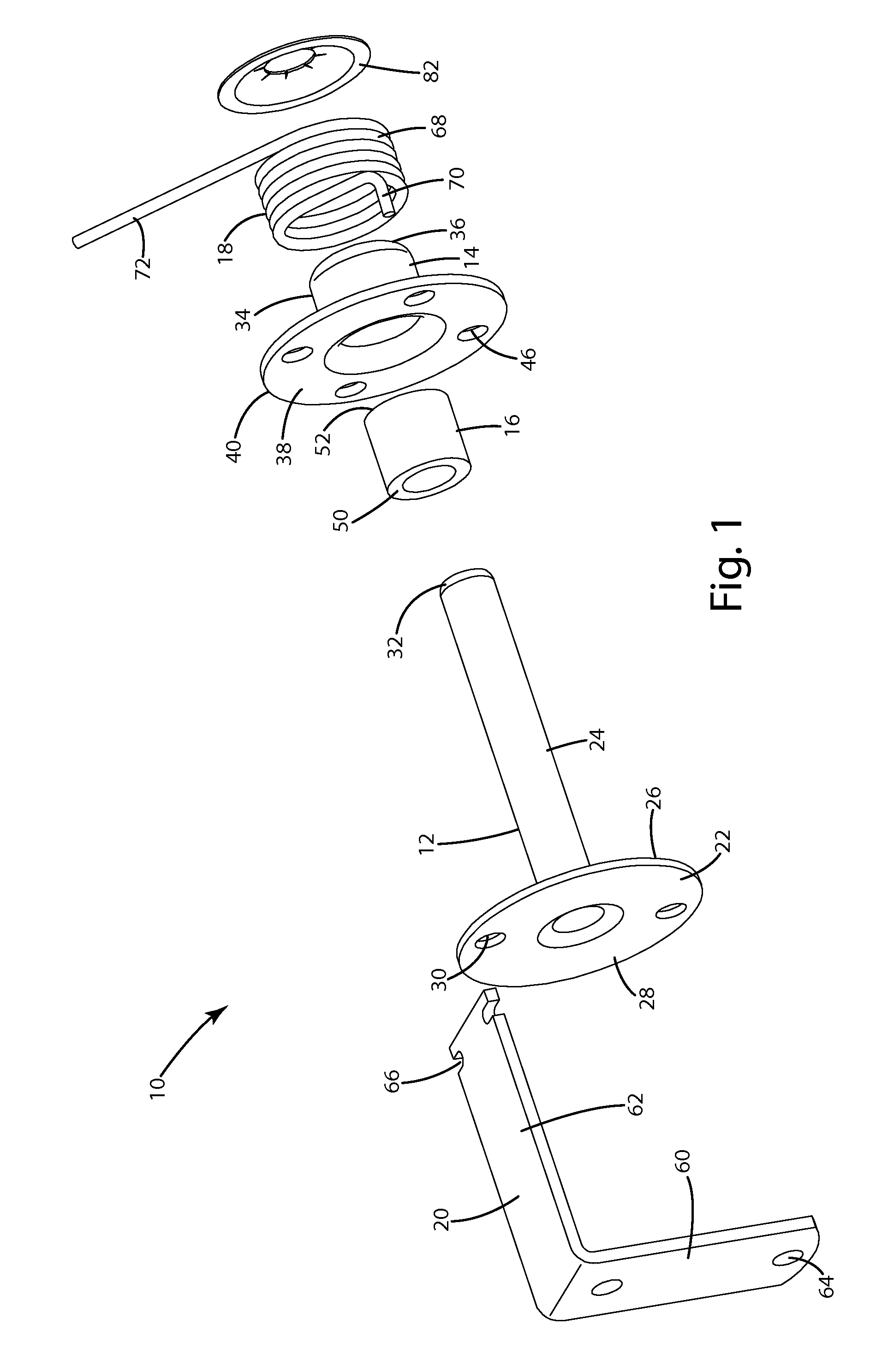
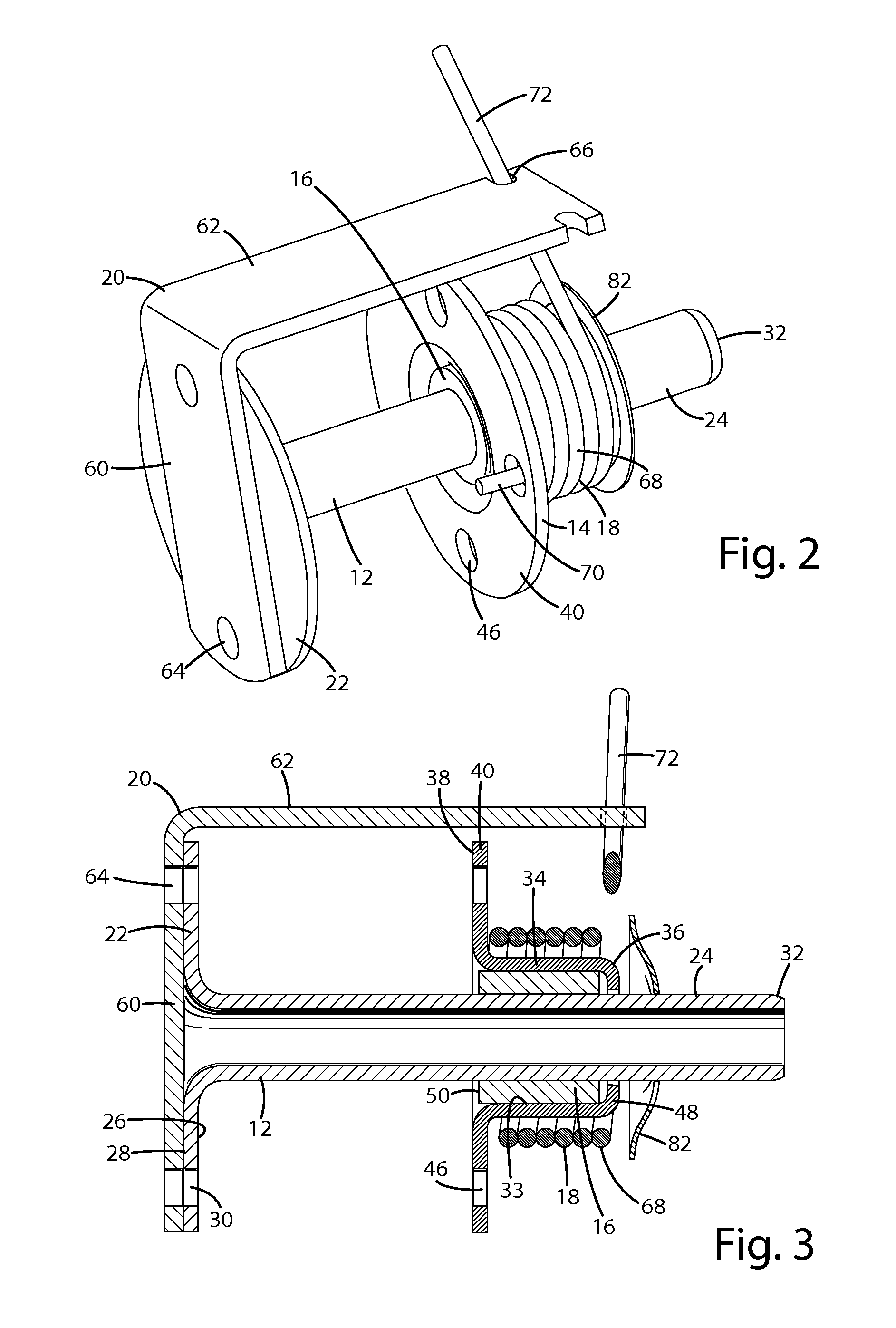
[0022]A torque assembly according to one embodiment of the present invention is shown in FIG. 1 and generally designated 10. The torque assembly forms a torque hinge that provides resistance throughout the range of motion for a hinged object. In the illustrated embodiment, the torque assembly includes a spindle 12, a cap 14 and a sleeve 16. The cap 14 is mounted on the spindle 12 for rotation about the spindle 12, and the sleeve 16 is positioned between the cap 14 and the spindle 12 to form a friction fit between the sleeve 16 and the spindle 12. In the embodiment shown in FIGS. 1-3 and 7-8, the torque assembly further includes a torsion spring 18 and a spring bracket 20. Throughout this description, directional terms, such as “vertical,”“horizontal,”“top,”“bottom,”“upper,”“lower,”“inner,”“inwardly,”“outer” and “outwardly,” may be used to assist in describing the invention based on the orientation of the embodiments shown in the illustrations. The use of directiona...


PUM

PropertyMeasurementUnit
time periodaaaaaaaaaa
angleaaaaaaaaaa
torqueaaaaaaaaaa

Abstract

A torque assembly includes a spindle, a cap mounted on the spindle for rotation about the spindle, and a work-hardened, plastic sleeve inserted between the cap and the spindle for constant rotation of the sleeve and cap with respect to the spindle. The torque assembly may be installed onto a hinged object and fixed object with movement along a single axis. The torque assembly may be formed by: (a) providing a spindle having a base and a rod extending from the base; (b) providing a cap member with an annular section defining an inner diameter; (c) providing an annular plastic sleeve having an inner diameter and an outer diameter; (d) work-hardening the sleeve for a predetermined time period; (e) changing the inner diameter of the sleeve; and (f) inserting the spindle rod through the inner diameter of the sleeve.

Description

BACKGROUND OF THE INVENTION[0001]The present invention relates to torque devices, and more particularly to a torque assembly that enables constant, controlled torque for a hinged object.[0002]Torque hinges are well known in a variety of applications. In general, a torque hinge provides a degree of resistance throughout the range of motion of a hinged object. In automobiles, torque hinges are commonly used to control the movement of objects such as storage compartment lids, sun visors, grab handles, and movable armrests. Other common applications include hinged portions of electronic devices, such as laptop computers.[0003]One common style of torque hinge is a spring torque hinge, which typically includes a torsion spring wound around a shaft. The ends of the torsion spring are fixed in position to compress the coiled spring about the shaft, creating a friction fit between the spring and the shaft that creates resistance through the shaft's range of motion. Another torque hinge style...

Claims


Application Information

Patent Timeline
Patent Type & Authority Applications(United States)
IPC IPC(8): E05F1/12E05F1/08B23P13/00
CPCB60N2/4633B60N2/466B60N2/4686B60N2/4606E05D5/00Y10T16/5389G06F1/1681E05Y2900/606Y10T29/49622Y10T29/49609Y10T29/24E05D11/08B60N2/753B60N2/78B60N2/767B60N2/793
Inventor WEBER, JOSEPH H.SOTOK, PHILIP A.YUNG, TONY
Owner VENTURESOURCE SOLUTIONS
Why Eureka
Try Eureka