Variable height slide-out rack for appliance

a technology of adjustable height and slide-out rack, which is applied in the field of adjustable height slide-out racks, can solve the problems of time-consuming, burdensome removal and adjustment of existing racks, and achieve the effect of reducing user effort and tim

Active Publication Date: 2013-04-25
HAIER US APPLIANCE SOLUTIONS INC
View PDF9 Cites 0 Cited by
  • Summary
  • Abstract
  • Description
  • Claims
  • Application Information

AI Technical Summary

Benefits of technology

[0010]Advantageously, illustrative embodiments of the present invention provide the ability to adjust an appliance rack (e.g., an oven r

Problems solved by technology

It is known that some oven racks can be as heavy as 15-22 pounds, making this existing rack

Method used


Image

  • Variable height slide-out rack for appliance
  • Variable height slide-out rack for appliance
  • Variable height slide-out rack for appliance

Examples


Embodiment Construction

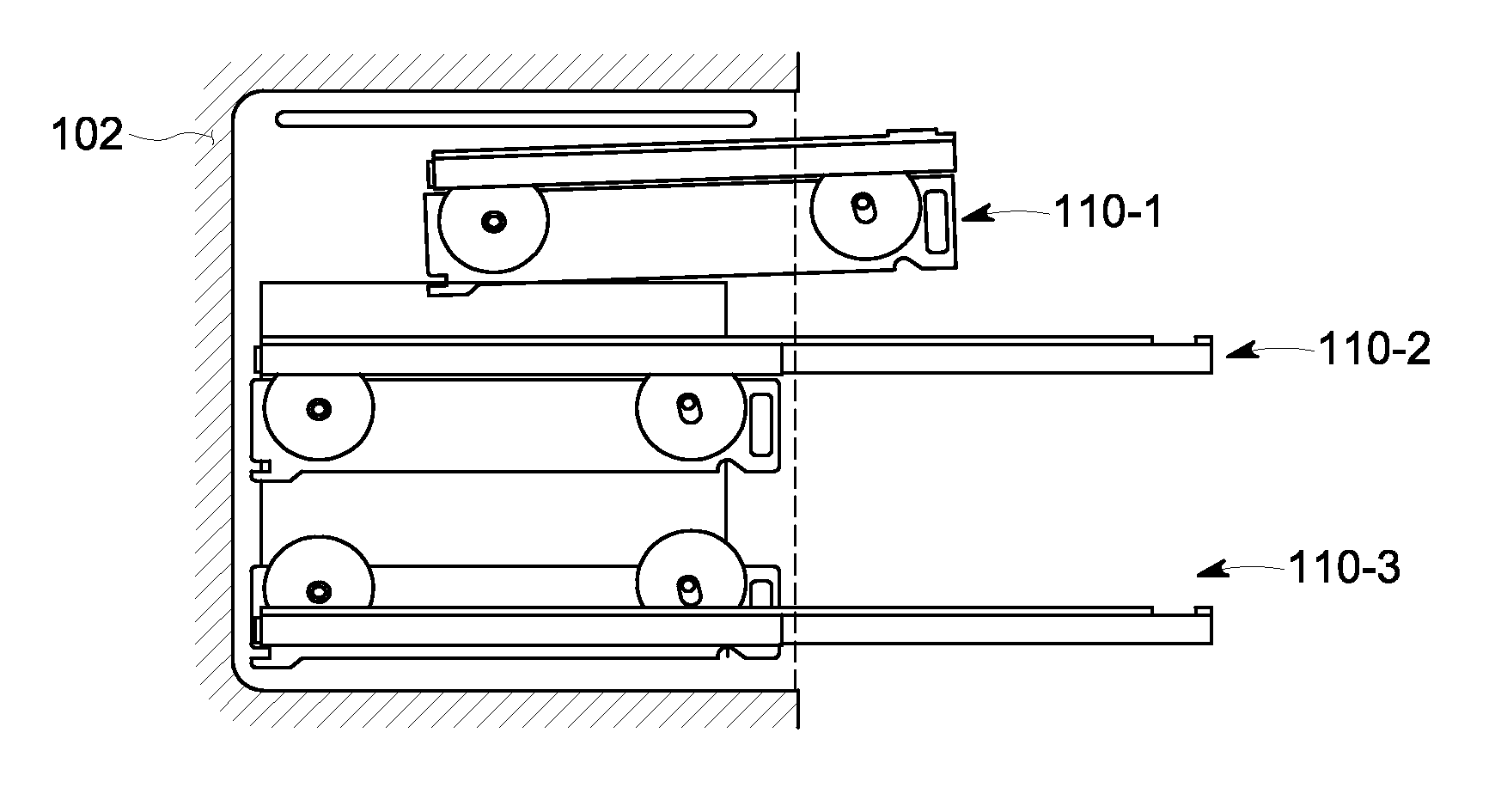
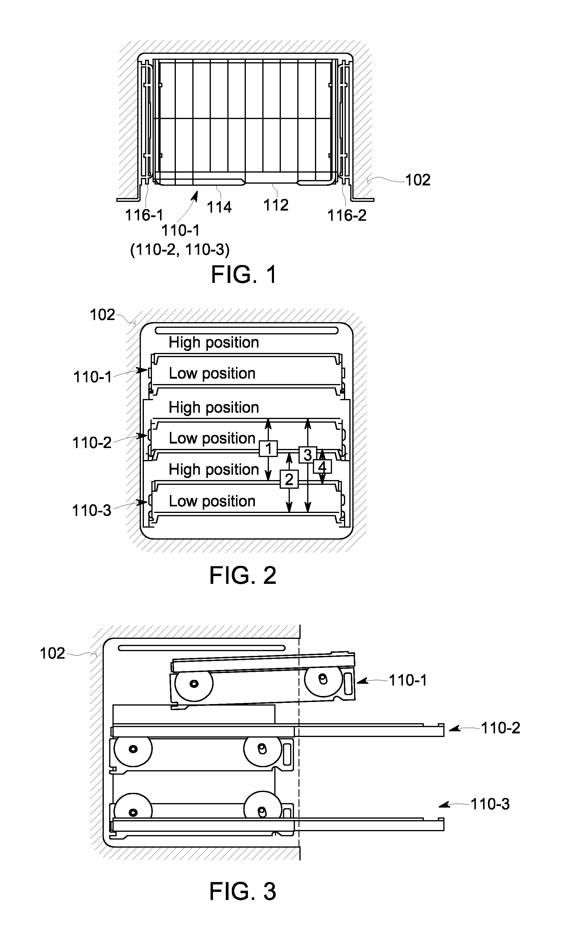
[0022]One or more illustrative embodiments of the invention will be described below in the context of an oven appliance. However, it is to be understood that embodiments of the invention are not intended to be limited to use with any particular appliances. Rather, embodiments of the invention may be applied to and deployed in any other suitable environment in which it would be desirable to provide for quick and easy height adjustment of a support shelf.

[0023]As illustratively used herein, the term “appliance” is intended to refer to a device or equipment designed to perform one or more specific functions. This may include, but is not limited to, equipment for consumer use, e.g., a wall-mounted oven, a freestanding cooking range, a refrigerator, a dishwasher, a microwave oven, etc. This may include, but is not limited to, any equipment that is useable in household or commercial environments.

[0024]Illustrative embodiments of the invention provide apparatus, systems and methods that pr...


PUM


Abstract

An apparatus includes a shelf and a support structure for supporting the shelf, the support structure including rotation features that cause the shelf to rotationally pivot from a first height position to a second height position in response to a user-provided force.

Description

BACKGROUND OF THE INVENTION[0001]The subject matter disclosed herein relates to appliances such as ovens, and more particularly to variable height slide-out racks for use in appliances such as ovens.[0002]Oven racks are shelves that support food and / or cookware containing food inside the oven compartment while the food cooks or is otherwise stored in the oven. Traditional oven racks are known to be removable and adjustable in height. Typically, there are horizontal channels or other supports formed on the inside walls of the oven that hold the rack in place at a given height. There are typically supports at different height positions to allow for more than one rack to be in the oven supporting the food / cookware at the same time, and for the one or more racks to be repositioned in height.[0003]Traditionally, to adjust the height of a rack, a consumer has to fully remove the rack from the oven compartment and then install it in a new rack height position. Depending on the location of ...

Claims


Application Information

Patent Timeline
IPC IPC(8): F24C15/16A47B81/00A47B96/02
CPCF24C15/16A47B2230/0007
Inventor MCDANIEL, AARON MATTHEWJOHNSON, ERIC SCOTT
Owner HAIER US APPLIANCE SOLUTIONS INC
Why Eureka
Try Eureka