Collapsible crane capable of being transported by container

a container and crane technology, applied in the direction of trolleys, load-engaging elements, hoisting equipment, etc., can solve the problems of difficult domestic transportation of conventional cranes, high labor intensity, and difficult manufacturing of heavy long-load cranes, so as to reduce transportation costs, reduce labor intensity, and reduce the volume of assembly

Inactive Publication Date: 2016-03-03
KG INC
View PDF0 Cites 0 Cited by
  • Summary
  • Abstract
  • Description
  • Claims
  • Application Information

AI Technical Summary

Benefits of technology

[0031]According to the preferred embodiment of the present invention, the girder includes the first girder of the left side, the second girder of the right side and the third girder of the middle side, wherein the first girder and the second girder are detachably connected to the flanges of the both ends of the third girder, and the components mounted on the first girder, the second girder and the third girder are collapsed to come into contact with the first girder, the second girder and the third girder. Therefore, because the girder is separated into the first girder, the second girder and the third girder, and the components, such as the saddles, the inspection deck and the walk way hand rail, mounted on the first girder, the second girder and the third girder are collapsed toward the girders so as to come into contact with the girders, it minimizes the volume of the assembly of the first girder, the second girder and the third girder, so that the girders can be packed in the space of the standardized container by units. Therefore, because the crane which is heavy, long and large can be disassembled and collapsed and packed in the container by units, the crane can be transported by a general container without any special transporting vehicle not only in the land route but also in the sea route, thereby remarkably reducing transporting costs and the transporting period.
[0032]Moreover, because the separated unit girders and the components collapsed to the unit girders are packed in the container by units, the components of the crane are not exposed to the outside, the crane is not damaged while the crane packed in the container by units is transported in the land route and in the sea route and while the crane is transshipped from the ground to the general transporting vehicle and from the general transporting vehicle to the general cargo ship.
[0033]Furthermore, the collapsible crane capable of being transported in the container according to the preferred embodiment of the present invention is packed and transported in the container during land transportation and marine transportation because it can be packed in the container even though it is a heavy and long loaded thing, thereby being transported with the minimum costs, time and manpower. Additionally, such packing and transporting can activate not only the domestic crane industry but also the crane trade among countries.
[0034]The collapsible crane capable of being transported in the container according to the preferred embodiment of the present invention can be easily disassembled and stored after being used. After the crane is disassembled into the first girder, the second girder and the third girder and the components mounted on the girders are collapsed, when the girders are packed in the container by units, the crane can be stored for a long time without being exposed to the outside. Therefore, in case that the crane is not needed, because the crane can be stored in safety after being disassembled, there is no need to abandon the expensive crane as scrap metals, and the crane according to the preferred embodiment of the present invention can remarkably reduce financial burdens because it is reusable after being stored as needed.

Problems solved by technology

Such a crane which is a heavy long loaded thing is difficult to be manufactured and requires lots of expenses, time and manpower in order to be transported.
Therefore, the conventional crane is not easy in domestic transport and installation, and particularly, causes lots of barriers in trading among countries.
In order to export the cranes abroad, conventionally, people use a sea route, but it requires a great deal of time and shipping expenses and causes a damage of the crane.
That is, in order to transport the crane from a domestic manufacturing factory to a port, it is impossible to transport the crane by general transport, but the crane must be specially transported by a special transporting vehicle.
Therefore, it requires a great deal of transporting expenses and time.
However, because such a special cargo ship runs irregularly, it is not easy to fix a transport date and it takes lots of transport costs.
Furthermore, the crane transported by the special cargo ship, such as the bulk carrier, must be transported to the designated place using a special transport vehicle from a port of a designated country, and hence, it also requires lots of transport costs and time.
The conventional method for transporting the crane has another problem in that some components of the crane are damaged by shock generated during transport.
While the crane which is a heavy long loaded thing is transported by the land route and the sea route and while the crane is transshipped from the ground to the special transporting vehicle and from the special transporting vehicle to the special cargo ship, the crane is exposed to the outside, and hence, some components of the crane are damaged while being bumped.
The conventional method for transporting the crane has another problem in that the crane is not reusable after being disassembled.
Because the conventional crane is heavy and very long and large, in fact, it is impossible to store it in safety after being disassembled.

Method used


Image

  • Collapsible crane capable of being transported by container
  • Collapsible crane capable of being transported by container
  • Collapsible crane capable of being transported by container

Examples


Embodiment Construction

[0052]Reference will be now made in detail to the preferred embodiment of the present invention with reference to the attached drawings.

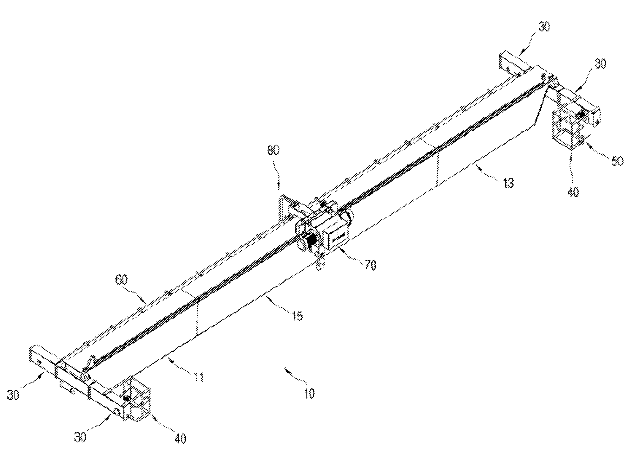
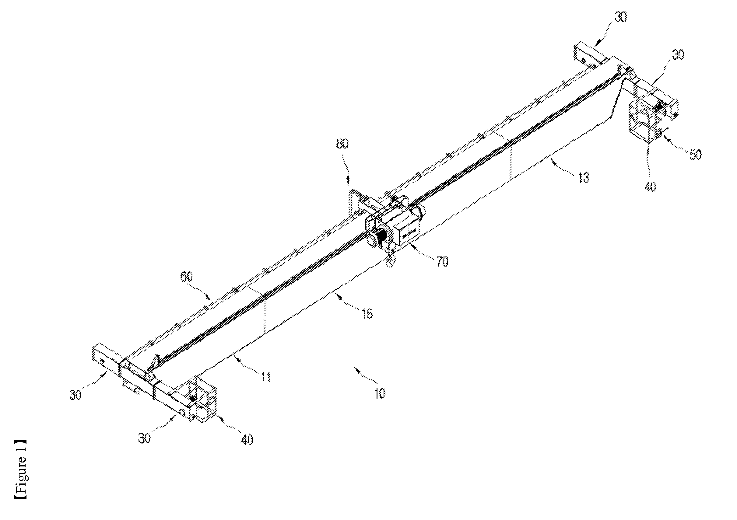
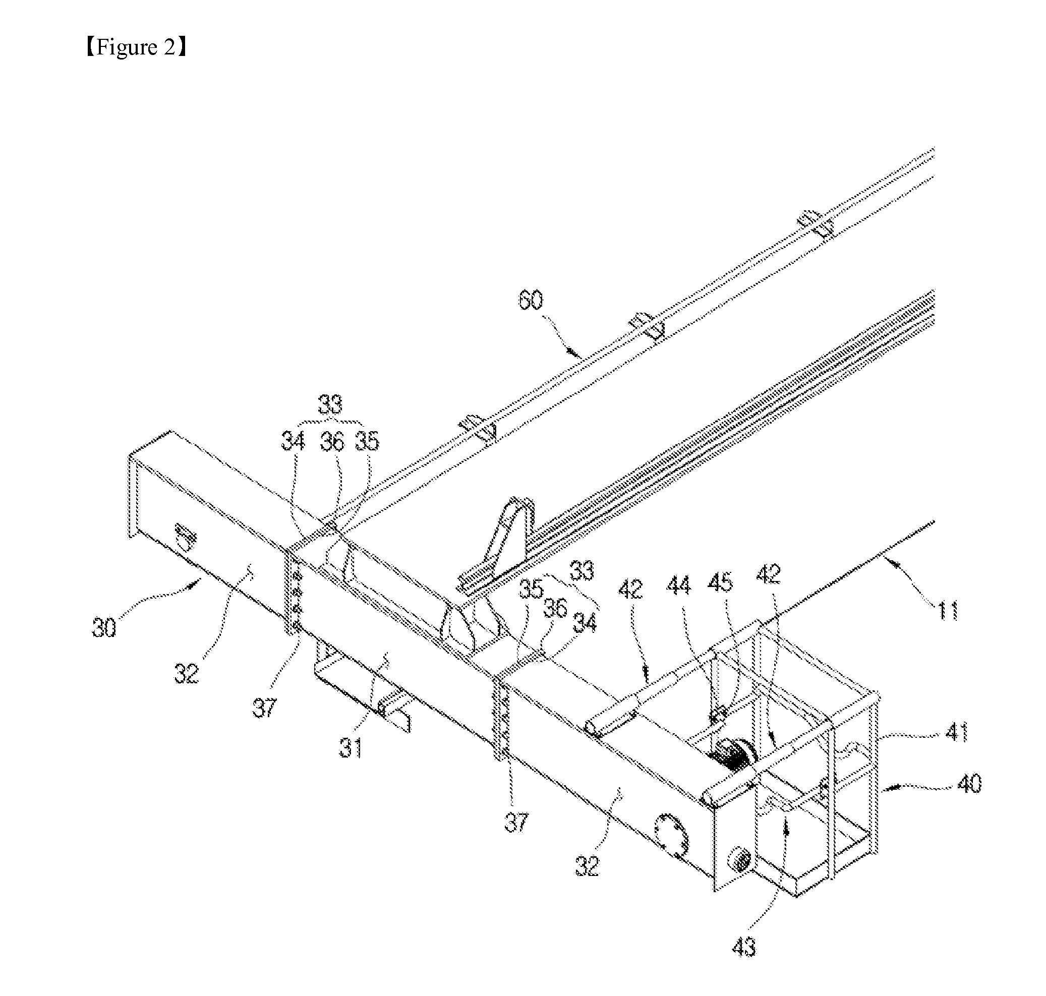
[0053]FIG. 1 is a schematic perspective view of a collapsible crane capable of being transported in a container according to a preferred embodiment of the present invention, FIG. 2 is a perspective view showing essential parts of a first girder, FIG. 3 is a perspective view showing essential parts of a second girder, FIG. 4 is a perspective view showing essential parts of a third girder, FIG. 5 is a plan view showing a separated state of the first girder, the second girder and the third girder, FIG. 6 shows a perspective view, a front view, a side view and a plan view showing a state where a saddle mounted on the first girder is collapsed toward the first girder, FIG. 7 shows a front view, a side view and a plan view showing a state where a saddle mounted on the second girder is collapsed toward the second girder, FIG. 8 shows front views and plan v...


PUM


Abstract

Disclosed therein is a collapsible crane capable of being transported by a container which includes a girder including a first girder of the left side, a second girder of the right side and a third girder of the middle side, the first girder and the second girder are detachably connected to flanges of the both ends of the third girder, and components mounted on the first girder, the second girder and the third girder are collapsed to come into contact with the first girder, the second girder and the third girder. Therefore, because the girder is separated into the first girder, the second girder and the third girder, and the components, such as saddles, inspection deck and a walk way hand rail, mounted on the first girder, the second girder and the third girder are collapsed toward the girders so as to come into contact with the girders, it minimizes the volume of the assembly of the first girder, the second girder and the third girder, so that the girders can be packed in the space of the standardized container by units. Therefore, because the crane which is heavy, long and large can be disassembled and collapsed and packed in the container by units, the crane can be transported by a general container without any special transporting vehicle not only in a land route but also in a sea route, thereby remarkably reducing transporting costs and the transporting period.

Description

TECHNICAL FIELD[0001]The present invention relates to a collapsible crane capable of being transported by a container. More specifically, each component of the collapsible crane is disposed separably or collapsibly, thereby being assembled after being transported in a state where it is accommodated in a small-sized container and being kept for re-use after being disassembled.BACKGROUND ART[0002]A crane is a machine or a device for lifting and horizontally transporting heavy things using electric power,[0003]and handles the heavy things in a three-dimensional space by actions to hoist and lower the heavy things, by actions to travel, transverse and rotate to horizontally move the hoisted heavy thing, and by combinations of the actions.[0004]Such a crane includes a pair of traveling rails, a girder mounted on the traveling rails to be conveyed along the rails, and a hoist mounted on the girder to be conveyed together with the girder.[0005]Traveling wheels are mounted at both ends of t...

Claims


Application Information

Patent Timeline
Patent Type & Authority Applications(United States)
IPC IPC(8): B66C19/02B66C17/00
CPCB66C19/02B66C17/00B66C5/04B66C11/00
Inventor CHO, DUCKRAE
Owner KG INC
Why Eureka
Try Eureka