Condensate secondary pan for a central air conditioning system

Inactive Publication Date: 2005-05-24
KAMINSKI KENNETH J
View PDF39 Cites 48 Cited by
  • Summary
  • Abstract
  • Description
  • Claims
  • Application Information

AI Technical Summary

Benefits of technology

[0008]The present invention provides a solution to these needs via a secondary pan which efficiently conveys all condensate to the secondary drain outlet without any unnecessary residual build-up of water on its inner surface. In order to facilitate the efficient removal o

Problems solved by technology

Because the drain line connector is integrally formed with the pan, there is no need for superf

Method used


Image

  • Condensate secondary pan for a central air conditioning system
  • Condensate secondary pan for a central air conditioning system
  • Condensate secondary pan for a central air conditioning system

Examples


first embodiment

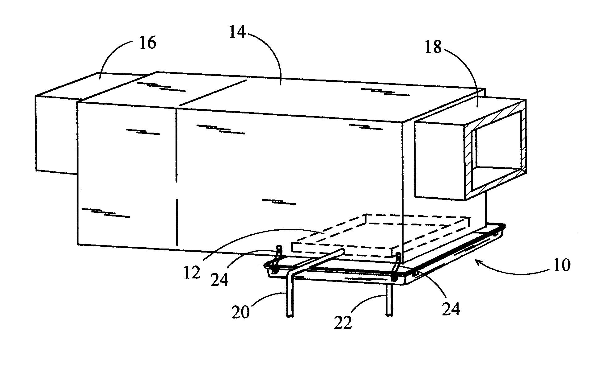
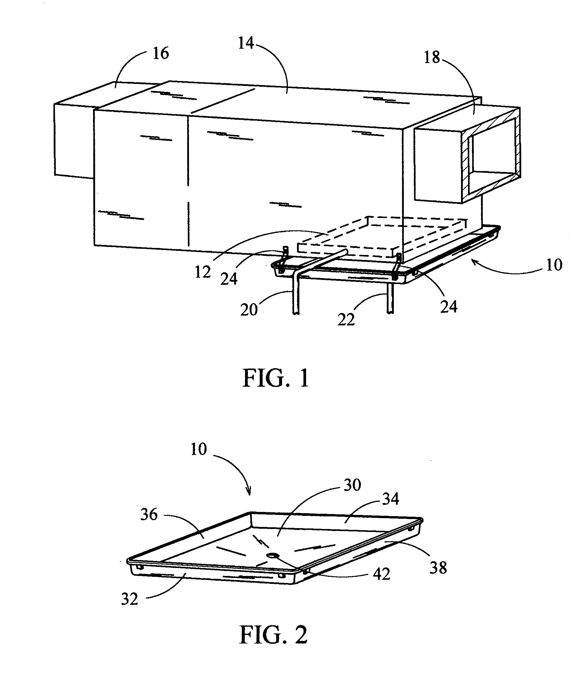
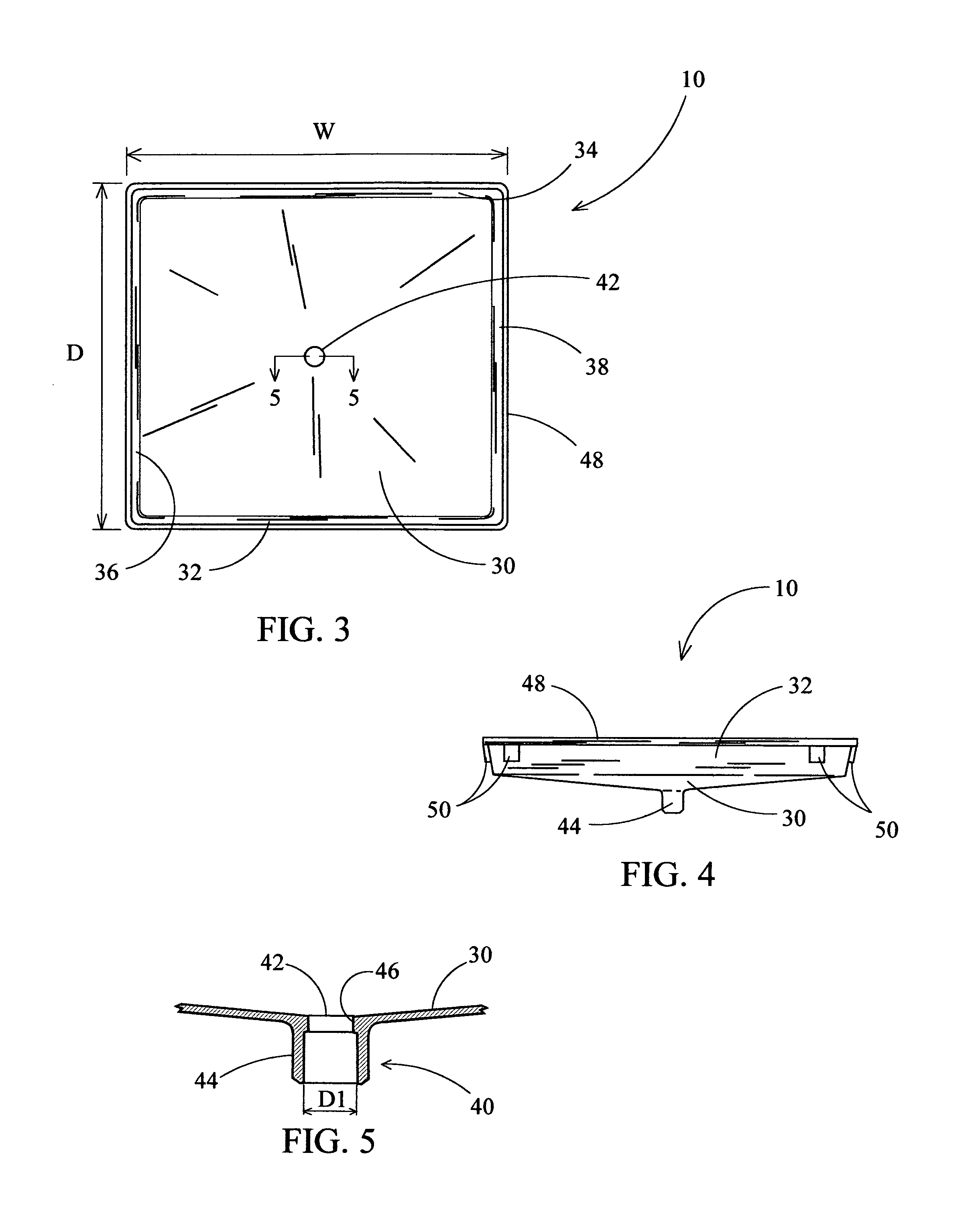
[0028]the present invention is shown in greater detail in FIGS. 2 through 4. As shown, the secondary pan 10 generally comprises a bottom panel 30 and integrally extending front 32, rear 34, left 36, and right 38 sidewalls. The bottom panel 30 is frustoconical in shape having a drain pipe connecting means 40, to be described later, integrally attached at its lower apex. The frustoconical shape of the bottom panel 30 insures that the outlet 42 formed by the opening in the drain pipe connecting means 40 always exists at the elevational lower extremity thereof in order to insure that condensate is not allowed to pool within the secondary pan 10. Although the bottom panel 30 disclosed herein is sloped toward the outlet using a frustoconical shape, it is well known in the art that other geometrical shapes may be used which creates a sloping surface from any point on the upper surface of the bottom panel 30 to the outlet 42 thereof.

[0029]FIG. 5 shows an enlarged elevational sectional view ...

embodiment 60

[0033]An alternative embodiment 60 of the present invention is shown in FIGS. 6 through 8 in which a condensate secondary pan has a drain pipe attachment means 66 integrally attached beneath the front sidewall 32 for installations desiring a side mounting configuration of the secondary drain pipe. The sidewalls (32, 34, 36, and 38), rib 48, and protrusions 50 as well as the material they are made of are similar in design and function to the embodiment of FIGS. 1–5. The embodiment of FIGS. 6–8 differ from that of FIGS. 1–5 in that a lower sidewall portion 62 is integrally attached to the bottom edge of the front sidewall 32 and is generally coplanar therewith. In addition, the bottom panel 64 is generally curved in shape thus having a downward slope along its entire upper surface towards the center of the lower sidewall portion 62. FIG. 9 shows an enlarged elevational sectional view of the present embodiment showing the configuration of the drain pipe connecting means 66 to the lower...


PUM


Abstract

A condensate secondary pan for a central air conditioning system is herein disclosed whereby overflow protection of the primary condensate removal system for a fan coil unit of a central air conditioning system is realized. The secondary pan is positioned directly beneath the primary pan of the central air conditioning system to convey condensate safely outside an enclosure should the primary pan overflow due to clogging of the primary drain line, or leak due to cracks or fissures formed in the primary pan. The condensate secondary pan has a predetermined girth sufficient to extend laterally beyond the primary pan of a conventional fan coil unit. The condensate secondary pan also has a bottom panel which is frustoconical in shape, thus minimizing the pooling of condensate on its surface as well as an integral drain pipe connecting means, thereby eliminating the need for a superfluous user supplied connecting means which is typically made of metal and thus is susceptible to corrosion.

Description

CROSS-REFERENCE TO RELATED APPLICATIONS[0001]This application claims priority under 35 U.S.C. 119(e) on U.S. Provisional application No. 60 / 435,756 Entitled “HORIZONTAL” ATTIC INSTALLED HVAC SYSTEM SECONDARY DRAIN PAN, filed on Dec. 23, 2002, by Kenneth J. Kaminski.FIELD OF THE INVENTION[0002]This invention relates to condensate overflow protection devices for central air conditioning systems, and more particularly, to a secondary pan which is non-corrosive and has a unique bottom contour which minimizes the pooling of condensate upon its bottom surface.BACKGROUND OF THE INVENTION[0003]Most homes today have some form of cooling system in order to make the living space therein more comfortable during the hot summer months. There are several types of cooling systems in use, however the most popular type used in the more humid climates is the “split” type refrigeration system more commonly known as a central air conditioning system. The central air conditioning system generally compris...

Claims


Application Information

Patent Timeline
IPC IPC(8): F24F13/22F24F13/00
CPCF24F13/222
Inventor KAMINSKI, KENNETH J.
Owner KAMINSKI KENNETH J
Why Eureka
Try Eureka