
Electrical connector assembly

Active Publication Date: 2013-04-25
HIROSE ELECTRIC GROUP
View PDF19 Cites 9 Cited by
  • Summary
  • Abstract
  • Description
  • Claims
  • Application Information

AI Technical Summary

Benefits of technology

The present invention provides a solution for improving the connection between power supply terminals and mating connectors by using an elastic tubular member. This elastic tubular member can be fitted to the outer circumferential surfaces of the power supply terminal and the mating connector, allowing for a more flexible connection that can withstand a range of angles and contact pressures while maintaining sufficient contact between the terminals. The elastic tubular member can be formed by rolling a metal plate into a tubular shape with multiple slits and an annular narrow portion, and can include a controlling portion to prevent excessive elastic displacement. The invention also provides a solution for ensuring a secure fit of the elastic tubular member to the outer circumferential surfaces of the power supply terminal and the mating connector.

Problems solved by technology

Second, in the conventional electrical connector assembly, the elastic piece is bent only in the thickness direction.
Accordingly, the length of the contact region tends to be insufficient.
In addition, it is difficult that the elastic pieces on the upper side and on the lower side are displaced elastically as being independent of each other.

Method used


Image

  • Electrical connector assembly
  • Electrical connector assembly
  • Electrical connector assembly

Examples


first embodiment

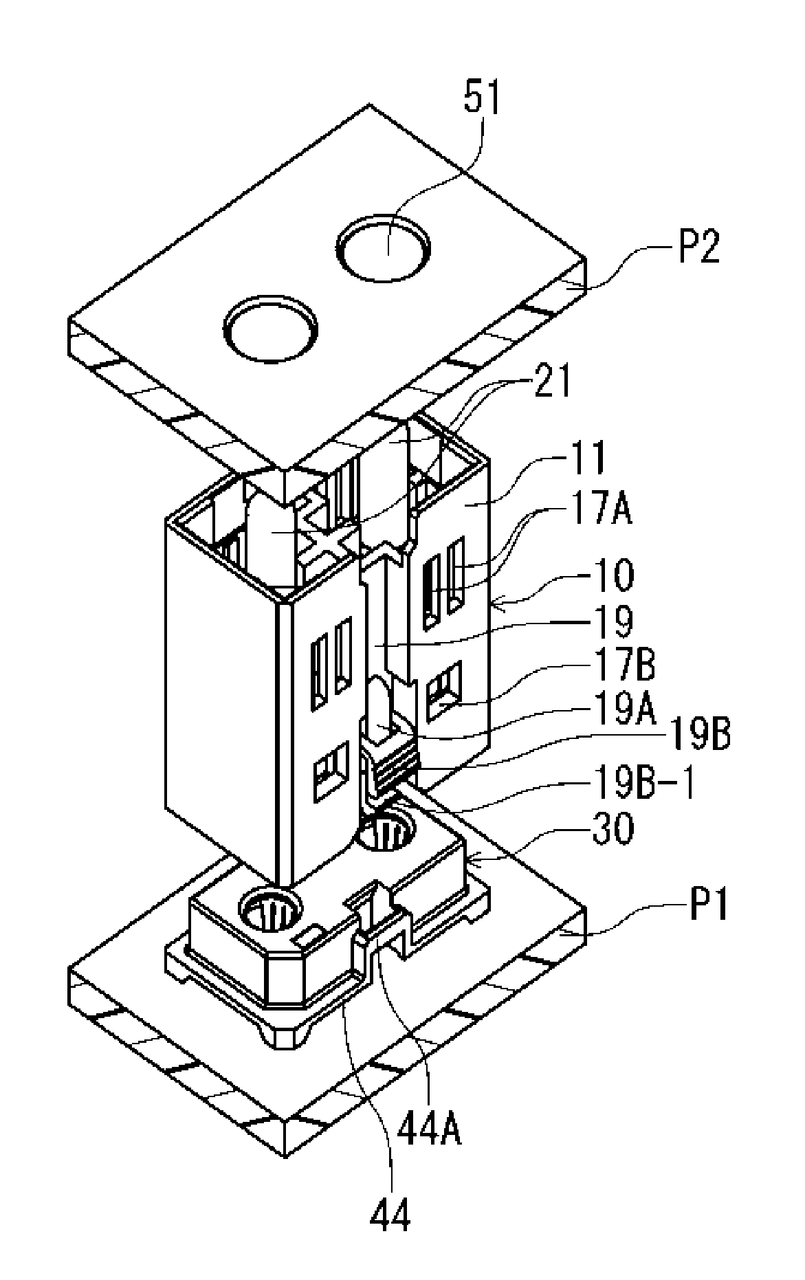
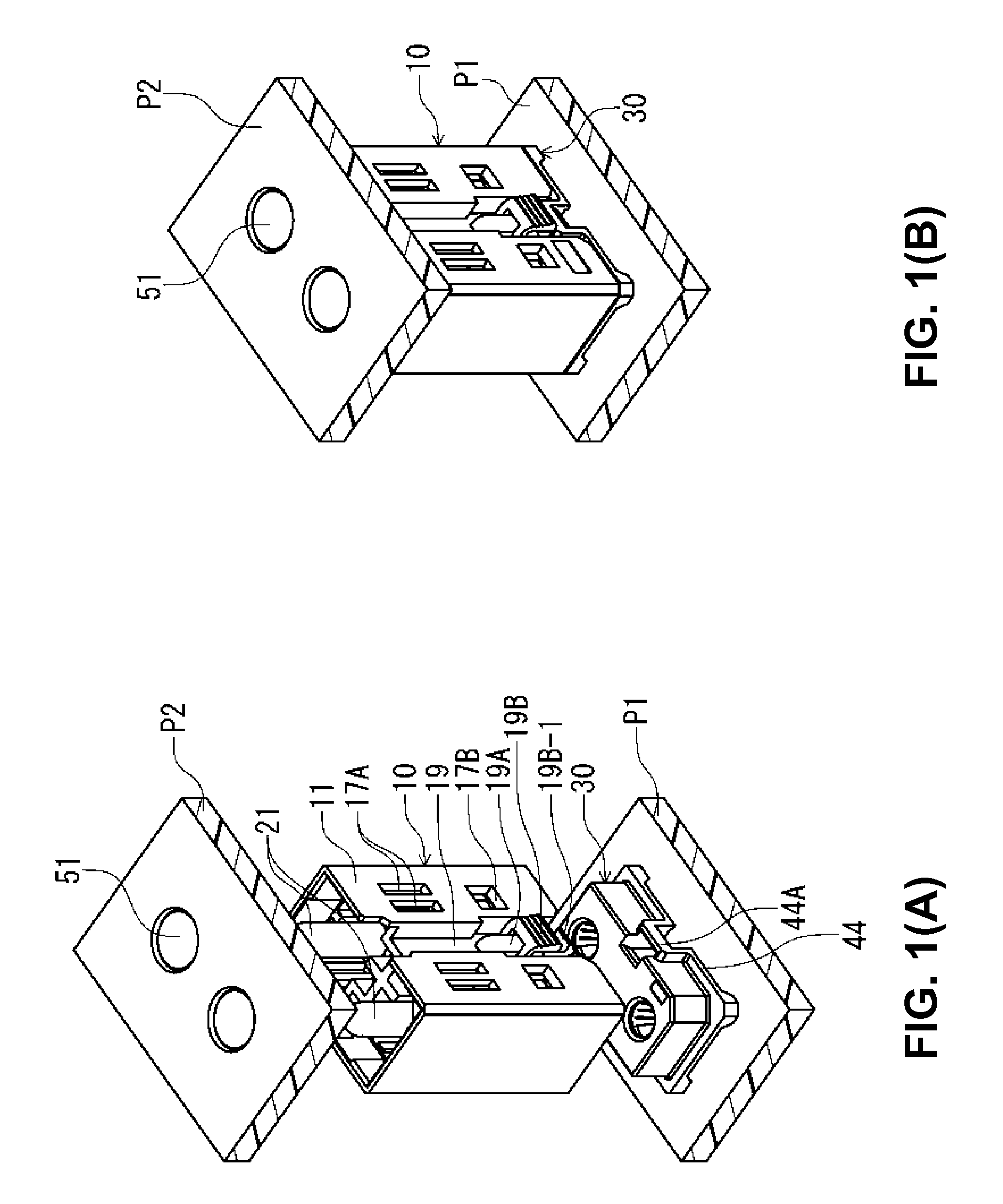
[0035]A first embodiment of the present invention will be explained. FIGS. 1(A) and 1(B) are perspective views showing an electrical connector assembly according to the first embodiment of the present invention. FIG. 1(A) shows an intermediate connector 10, a first mating connector 30 and a second mating connector 50 of the electrical connector assembly in a state of before being connected to each other. FIG. 1(B) shows the intermediate connector 10, the first mating connector 30 and the second mating connector 50 of the electrical connector assembly in a state of after being connected to each other.

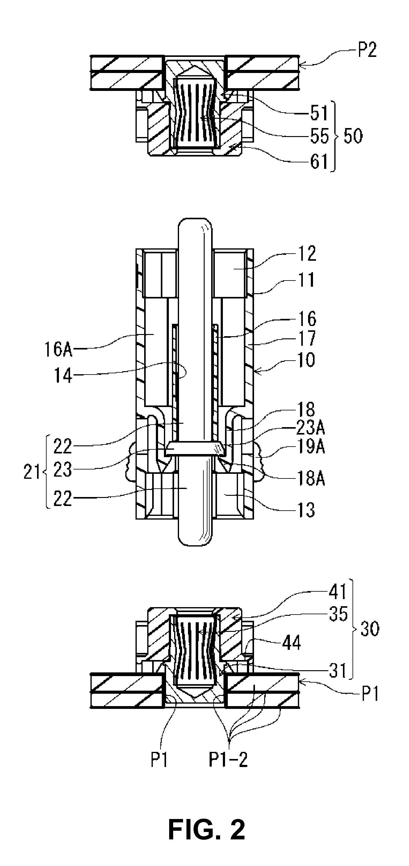
[0036]FIG. 2 is a longitudinal sectional view showing the electrical connector assembly taken along a direction perpendicular to a direction in which power supply terminals are arranged, according to the first embodiment of the present invention. FIG. 3 is a longitudinal sectional view showing the electrical connector assembly taken along the direction the power supply terminals are arra...

second embodiment

[0076]Next, a second embodiment of the present invention will be explained. As shown in FIGS. 1(A), 1(B) and 6, in the first embodiment, the elastic tubular members 35, 55 are respectively provided in the first mating connector 30 and the second mating connector 50. In the present invention, the elastic tubular member 35 may be provided in the intermediate connector 10, not limited to the first embodiment.

[0077]FIG. 7 is a longitudinal sectional view showing an intermediate connector 10, a first mating connector 30 and the second mating connector 50 of an electrical connector assembly according to the second embodiment of the present invention. FIG. 8 is a front view showing an elastic tubular member 37 and the power supply terminal 21 of the intermediate connector 10 of the electrical connector assembly according to the second embodiment of the present invention.

[0078]As shown in FIG. 7, the elastic tubular member 37 is attached to the power supply terminal 21 of the intermediate c...


PUM


Abstract

An electric connector assembly includes an intermediate connector for connecting the first attaching connector to the second attaching connector. The intermediate connector includes a power source terminal. The first attaching connector includes a first receiving terminal for contacting with the power source terminal, and the second attaching connector includes a second receiving terminal for contacting with the power source terminal. One of the first receiving terminal and the power source terminal and one of the second receiving terminal and the power source terminal include a metal cylindrical member capable of elastically deforming in a radial direction. Therefore, the power source terminal can incline and move in the radial direction at an arbitrary angle along a circumferential direction around an axial line of the power source terminal. The elastic cylindrical member includes a circumference elastically contacting with the power source terminal, the first receiving terminal, and the second receiving terminal.

Description

BACKGROUND OF THE INVENTION AND RELATED ART STATEMENT[0001]The present invention relates to an electrical connector assembly. More specifically, the present invention relates to an electrical connector assembly including a power supply terminal.[0002]Patent Reference 1 has disclosed a conventional electrical connector assembly. The conventional electrical connector assembly disclosed in Patent Reference 1 includes a mating connector attached to a circuit board and an intermediate connector for connecting the mating connector to another mating connector attached to another circuit board.[0003]In the conventional electrical connector assembly, each of the mating connectors includes a fixed contact (a terminal) having a pin shape and extending in a connecting direction of the mating connectors. A plurality of the fixed contacts is planted in multiple places forming rows and columns on a plane perpendicular to the connecting direction. The intermediate connector includes a movable conta...

Claims


Application Information

Patent Timeline
IPC IPC(8): H01R13/627
CPCH01R12/7088H01R13/187H01R12/91H01R12/73
Inventor AIMOTO, DAIKI
Owner HIROSE ELECTRIC GROUP
Learn More